


SLUU195 − June 2004
14
TPS40090 Multi-Phase Buck Converter and TPS2834 Drivers Steps-Down from 12-V to 1.5-V at 100 A
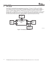
5 Test Setup
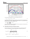
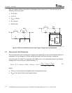
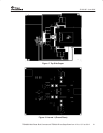
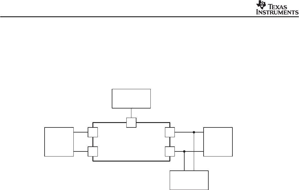
The HPA072 has the following input/output connections: 12-V input J1 (VIN) and J2 (GND),
1.5-V output J9 (VOUT) and J10 (GND). A diagram showing the connection points is shown in
Figure 5. A power supply capable of supplying 18 A should be connected to VIN and GND
through a pair of 10 AWG wires. The 1.5-V load should be connected respectively to J9 and J10
through pairs of 0 AWG wires. Wire lengths should be minimized to reduce losses in the wires.
A 5-inch fan with 200-cfm air flow is recommended to operate this board at full load.
TPS40090EVM−002
Board
J1
J2
J9
J10
Oscilloscope
CH1
J8
Electronic
Load
Fluke 45
12 V/ 20 A
Power
Supply
UDG−04063
V
OUT
DC
Figure 7. Connections for the Test