


SLUU195 − June 2004
9
TPS40090 Multi-Phase Buck Converter and TPS2834 Drivers Steps-Down from 12-V to 1.5-V at 100 A
0
0.1
0.2
0.5
0.6
0.4
0.3
0 10 20304050 60708090100
Duty Cycle − %
I
RMS_CIN(nom)
− Normalized RMS Input − A
N
PH
= 1
N
PH
= 2
N
PH
= 3
N
PH
= 4
N
PH
= 6
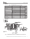
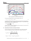
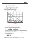
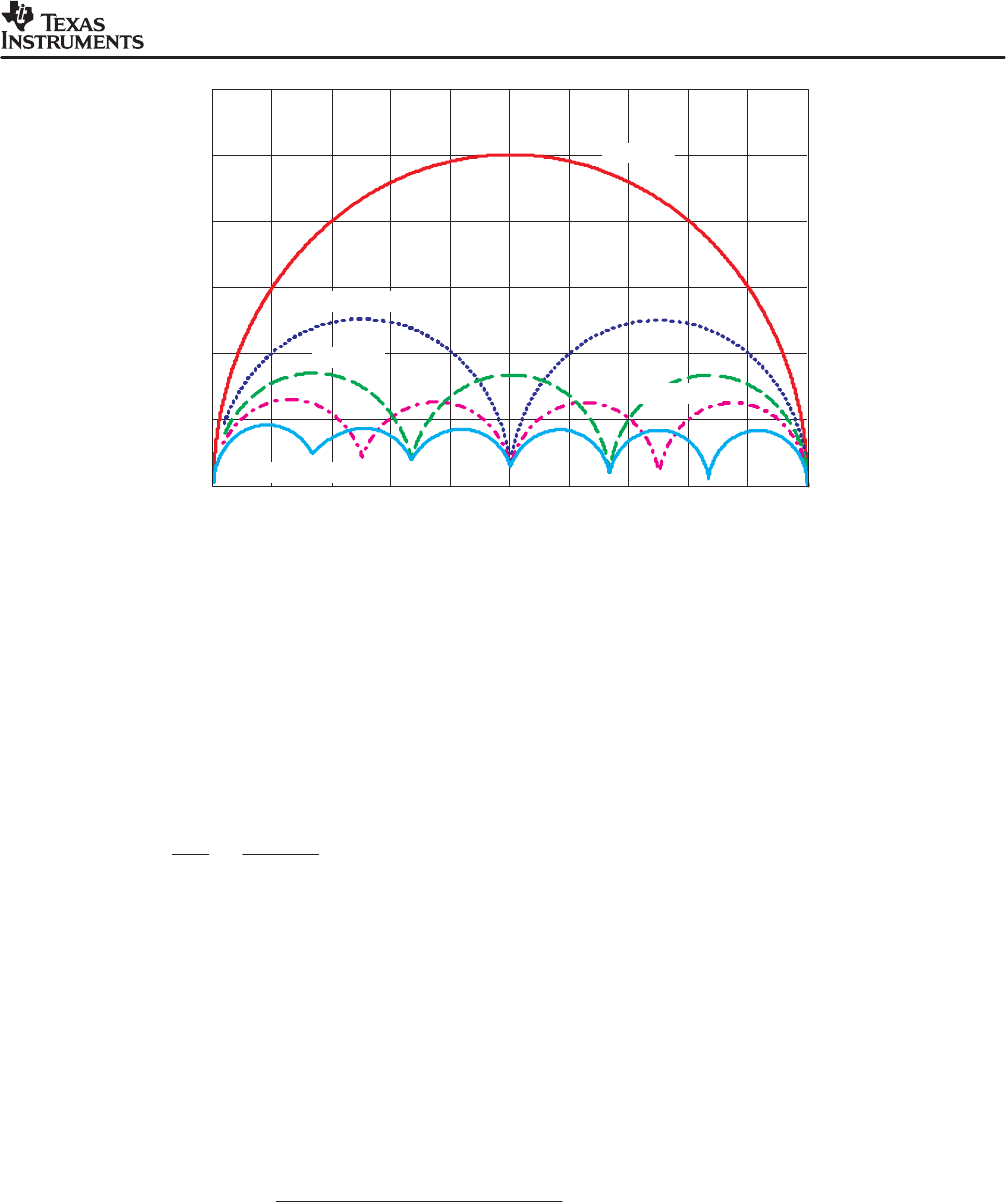
Figure 4. Input Ripple Current RMS Value Overload Current
The maximum input ripple RMS current can be estimated as shown in (4).
I ^ I
OUT
D I
IN(nom)
ǒ
4, D
min
Ǔ
+ 3.18 A
It is also important to consider a minimum capacitance value which limits the voltage ripple to a
specified value if all the current is supplied by the onboard capacitor. For a typical ripple voltage
of 150 mV the maximum ESR is calculated in (5) as:
ESR +
D V
D I
+
150 mV
3.18 A
+ 47 mW
Two 68-µF, 20-V Oscon capacitors (20SVP68M) from Sanyo are placed on the input side of the
board. The ESR is 40 mΩ for each capacitor.
4.4 Output Ripple Cancellation and Capacitor Selection
Due to the interleaving of channels, the total output ripple current is smaller than the ripple
current from a single phase. The ripple cancellation factor is expressed in equation (6).
DI
OUT
ǒ
N
PH
,D
Ǔ
+
ǒ
N
PH
P
i + 1
Ť
i * N
PH
D
Ť
Ǔ
ƪ
N
PH
*1
P
i + 1
ǒ
Ť
i * N
PH
D
Ť
) 1
Ǔ
ƫ
k
ǒ
N
PH
,D
Ǔ
+ if
ǒ
N
PH
v 1, DI
OUT
(D), DI
OUT
ǒ
N
PH
,D
Ǔ
Ǔ
(4)
(5)
(6)