


SLUU195 − June 2004
18
TPS40090 Multi-Phase Buck Converter and TPS2834 Drivers Steps-Down from 12-V to 1.5-V at 100 A
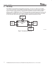
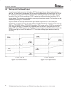
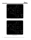
6.5 Start up with Pre-Biased Output
In synchronous buck converter, the bottom FET discharges the pre-biased output during
start-up. To avoid this, a comparator U9 and surround components are used to pull the SYNC
pin of the drivers low, which keeps the bottom FET off during startup. So the output can rise
smoothly. After the SS pin comes up, SYNC is pulled up high and enable the bottom FET’s
driving signal. The converter goes back to normal synchronization mode. This function can be
enabled by shorting J11 on the board.
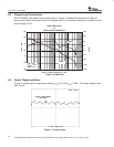
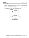
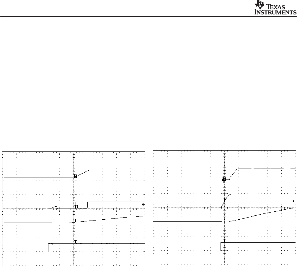
Figure 8 shows the start-up waveform with pre−biased output with J11 short and open
respectively. In Figure 12, there are two glitches of SYNC waveform. The first one is cause by
P5V from TPS40090. When TPS40090 is enabled, P5V comes up first. SYNC is connected to
P5V through a divider. The second one happens when the driver is ready and turns on the
bottom FET when PWM signal is low. So the pre-biased output is pulled low which causes the
SYNC signal high to turn off the bottom FET. Then output voltage goes back and rises up
smoothly.
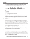
Figure 13. J11 Short Circuit
V
OUT
(2 V/div)
t − Time − 1 ms / div
V
SYNC
(2 V/div)
V
SS
(5 V/div)
V
EN
(2 V/div)
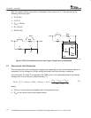
Figure 14. J11 Open Circuit
t − Time − 2.5 ms / div
V
OUT
(2 V/div)
V
SYNC
(5 V/div)
V
SS
(5 V/div)
V
EN
(2 V/div)