


SLUU195 − June 2004
16
TPS40090 Multi-Phase Buck Converter and TPS2834 Drivers Steps-Down from 12-V to 1.5-V at 100 A
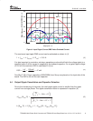
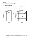
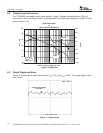
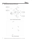
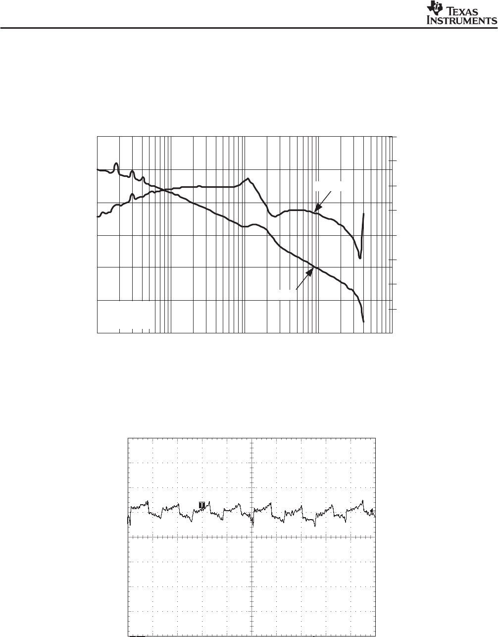
6.2 Closed-Loop Performance
The TPS40090 uses peak current-mode control. Figure 10 shows the bode plots at 100 A of
load current, where no droop function is implemented. The crossover frequency is at 89 kHz with
phase margin of 40°.
100
0
−40
1 k 10 k 100 k 1 M
80
60
40
20
−20
180
45
135
90
0
−45
−135
−180
−90
GAIN AND PHASE
vs
OSCILLATOR FREQUENCY
PHASE
GAIN
f
OSC
− Oscillator Frequency − kHz
Gain − dB
Phase − 5
V
IN
= 12 V
V
OUT
= 1.5 V
I
OUT
= 10 A
Figure 10. Bode Plot
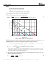
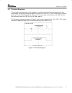
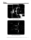
6.3 Output Ripple and Noise
Figure 11 shows typical output noise where V
IN
=12 V, and I
OUT
=100A. The output ripple is less
than 10 mV.
I
OUT
= 100 A
t − Time − 500 ns / div
Output Voltage Ripple
(10 mV/div)
Figure 11. Output Noise