


SLUU195 − June 2004
7
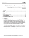
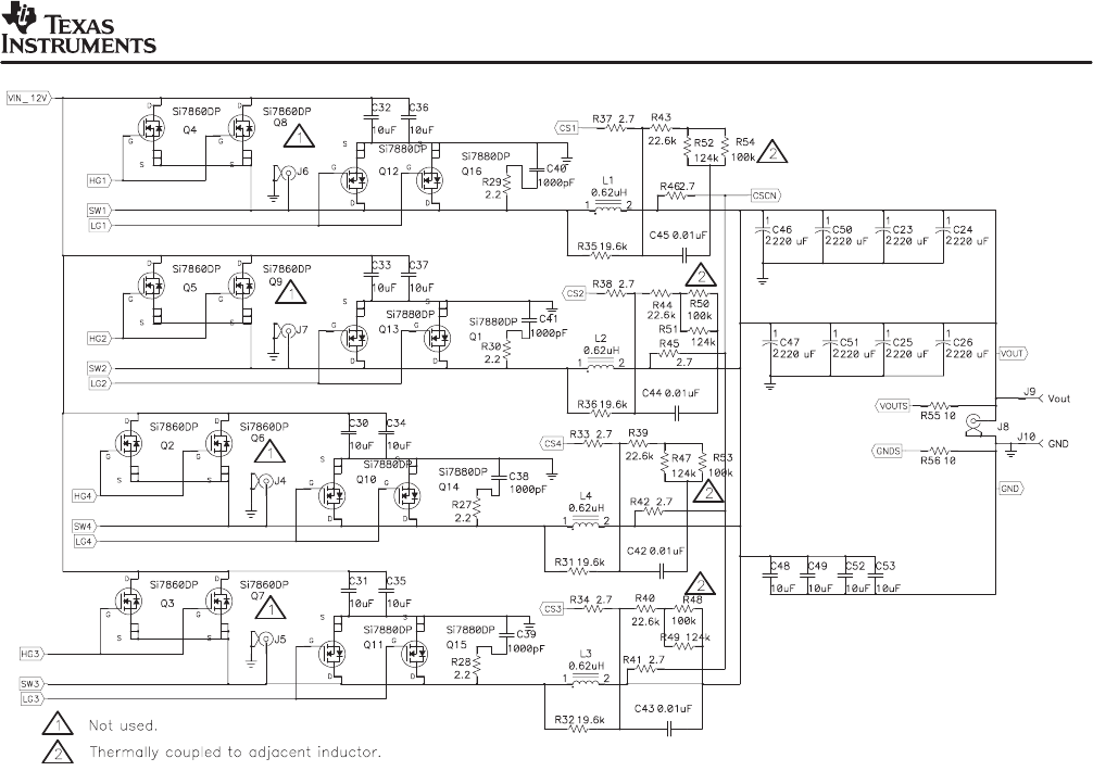
TPS40090 Multi-Phase Buck Converter and TPS2834 Drivers Steps-Down from 12-V to 1.5-V at 100 A
+ +
+
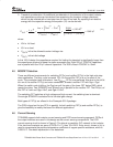
1.5V/100A
+ +
+ + +
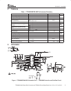
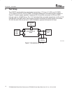
Figure 3. TPS40090EVM−002 Schematic Part 3 − Power Stage
4 Component Selection
4.1 Frequency of Operation
The clock oscillator frequency for the TPS40090 is programmed with a single resistor from RT
(pin 16) to signal ground. Equation (1) from the datasheet allows selection of the R
T
resistor in
kΩ for a given switching frequency in kHz.
R
T
+ R12 + K
PH
ǒ
39.2 10
3
f
*1.024
PH
* 7
Ǔ
(
kW
)
where
• K
PH
is the coefficient that depends on the number of active phases
• f
PH
is the single phase frequency, in kHz
• for 2-phase and 3-phase configurations K
PH
=1.333
• for 4-phase K
PH
=1.0 is a single phase frequency, kHz.
The R
T
resistor value is returned by the last expression in kΩ. For 420 kHz, R
T
is calculated as
65.8 kΩ and a resistor with a 64.9-kΩ standard value is used.
(1)