


2–6
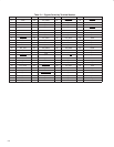
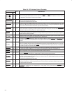
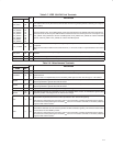
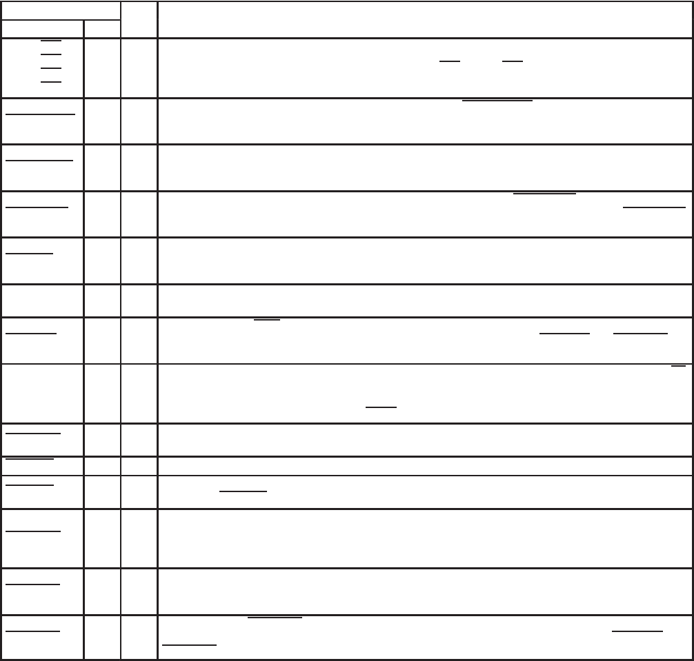
Table 2–6. PCI Interface Control Terminals
TERMINAL
I/O
DESCRIPTION
NAME NO.
I/O
DESCRIPTION
PCI_C/BE0
PCI_C/BE1
PCI_C/BE2
PCI_C/BE3
65
53
41
28
I/O
PCI bus commands and byte enables. The command and byte enable signals are multiplexed on the same PCI
terminals. During the address phase of a bus cycle PCI_C/BE3
–PCI_C/BE0 defines the bus command. During
the data phase, this 4-bit bus is used as byte enables.
PCI_CLKRUN 7 I/O
Clock run. This terminal provides clock control through the PCI_CLKRUN protocol. An internal pulldown
resistor is implemented on this terminal.
This terminal is implemented as open-drain.
PCI_DEVSEL 47 I/O
PCI device select. The TSB12LV26 asserts this signal to claim a PCI cycle as the target device. As a PCI
initiator, the TSB12LV26 monitors this signal until a target responds. If no target responds before time-out
occurs, then the TSB12LV26 terminates the cycle with an initiator abort.
PCI_FRAME 43 I/O
PCI cycle frame. This signal is driven by the initiator of a PCI bus cycle. PCI_FRAME is asserted to indicate
that a bus transaction is beginning, and data transfers continue while this signal is asserted. When PCI_FRAME
is deasserted, the PCI bus transaction is in the final data phase.
PCI_GNT 14 I
PCI bus grant. This signal is driven by the PCI bus arbiter to grant the TSB12LV26 access to the PCI bus after
the current data transaction has completed. This signal may or may not follow a PCI bus request, depending
upon the PCI bus parking algorithm.
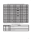
PCI_IDSEL 29 I
Initialization device select. IDSEL selects the TSB12LV26 during configuration space accesses. IDSEL can be
connected to one of the upper 24 PCI address lines on the PCI bus.
PCI_IRDY 44 I/O
PCI initiator ready. IRDY indicates the ability of the PCI bus initiator to complete the current data phase of the
transaction. A data phase is completed upon a rising edge of PCLK where both PCI_IRDY
and PCI_TRDY are
asserted.
PCI_PAR 52 I/O
PCI parity. In all PCI bus read and write cycles, the TSB12LV26 calculates even parity across the AD and C/BE
buses. As an initiator during PCI cycles, the TSB12LV26 outputs this parity indicator with a one PCI_CLK delay.
As a target during PCI cycles, the calculated parity is compared to the initiator parity indicator; a miscompare
can result in a parity error assertion (PCI_PERR
).
PCI_PERR 49 I/O
PCI parity error indicator. This signal is driven by a PCI device to indicate that calculated parity does not match
PCI_PAR when PERR_ENB (bit 6) is set in the PCI command register (offset 04h, see Section 3.4).
PCI_PME 17 O Power management event. This terminal indicates wake events to the host.
PCI_REQ 15 O
PCI bus request. Asserted by the TSB12LV26 to request access to the bus as an initiator. The host arbiter
asserts the PCI_GNT
signal when the TSB12LV26 has been granted access to the bus.
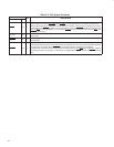
PCI_SERR 51 O
PCI system error. When SERR_ENB (bit 8) in the PCI command register (offset 04h, see Section 3.4) is set
the output is pulsed, indicating an address parity error has occurred. The TSB12LV26 needs not be the target
of the PCI cycle to assert this signal.
This terminal is implemented as open-drain.
PCI_STOP 48 I/O
PCI cycle stop signal. This signal is driven by a PCI target to request the initiator to stop the current PCI bus
transaction. This signal is used for target disconnects, and is commonly asserted by target devices which do
not support burst data transfers.
PCI_TRDY 45 I/O
PCI target ready. PCI_TRDY indicates the ability of the PCI bus targer to complete the current data phase of
the transaction. A data phase is completed upon a rising edge of PCI_CLK where both PCI_IRDY
and
PCI_TRDY
are asserted.