


4–17
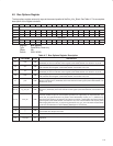
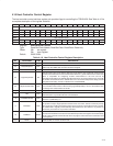
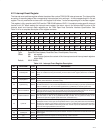
4.21 Interrupt Event Register
The interrupt event set/clear register reflects the state of the various TSB12LV26 interrupt sources. The interrupt bits
are set by an asserting edge of the corresponding interrupt signal or by writing a 1 in the corresponding bit in the set
register. The only mechanism to clear a bit in this register is to write a 1 to the corresponding bit in the clear register.
This register is fully compliant with OHCI and the TSB12LV26 adds an OHCI 1.0 compliant vendor-specific interrupt
function to bit 30. When reading the interrupt event register, the return value is the bit-wise AND function of the
interrupt event and interrupt mask registers per the
1394 Open Host Controller Interface Specification
. See
Table 4–14 for a complete description of the register contents.
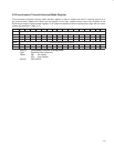
Bit 31 30 29 28 27 26 25 24 23 22 21 20 19 18 17 16
Name Interrupt event
Type R RSC R R R RSCU RSCU RSCU RSCU RSCU RSCU RSCU RSCU R RSCU RSCU
Default 0 X 0 0 0 X X X X X X X X 0 X X
Bit 15 14 13 12 11 10 9 8 7 6 5 4 3 2 1 0
Name Interrupt event
Type R R R R R R RSCU RSCU RU RU RSCU RSCU RSCU RSCU RSCU RSCU
Default 0 0 0 0 0 0 X X X X X X X X X X
Register: Interrupt event
Type: Read/Set/Clear/Update, Read/Set/Clear, Read/Update, Read-only
Offset: 80h set register
84h clear register [returns the content of the interrupt event and interrupt mask registers
when read]
Default: XXXX 0XXXh
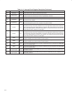
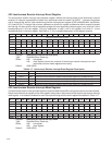
Table 4–14. Interrupt Event Register Description
BIT FIELD NAME TYPE DESCRIPTION
31 RSVD R Reserved. Bit 31 returns 0 when read.
30 vendorSpecific RSC
This vendor-specific interrupt event is reported when either of the general-purpose interrupts occur
which are enabled via INT3_EN and INT2_EN in the GPIO control register (offset FCh, see Section
3.23).
29–27 RSVD R Reserved. Bits 29–27 return 0s when read.
26 phyRegRcvd RSCU
The TSB12LV26 has received a PHY register data byte which can be read from the PHY layer control
register (OHCI offset ECh, see Section 4.30).
25 cycleTooLong RSCU
If bit 21 (cycleMaster) of the link control register (OHCI offset E0h/E4h, see Section 4.28) is set, then
this indicates that over 125 µs have elapsed between the start of sending a cycle start packet and the
end of a subaction gap. The link control register bit 21 (cycleMaster) is cleared by this event.
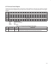
24 unrecoverableError RSCU
This event occurs when the TSB12LV26 encounters any error that forces it to stop operations on any
or all of its subunits, for example, when a DMA context sets its dead bit. While this bit is set, all normal
interrupts for the context(s) that caused this interrupt are blocked from being set.
23 cycleInconsistent RSCU
A cycle start was received that had values for cycleSeconds and cycleCount fields that are different
from the values in bits 31–25 (cycleSeconds field) and bits 24–12 (cycleCount field) of the
isochronous cycle timer register (OHCI offset F0h, see Section 4.31).
22 cycleLost RSCU
A lost cycle is indicated when no cycle_start packet is sent/received between two successive
cycleSynch events. A lost cycle can be predicted when a cycle_start packet does not immediately
follow the first subaction gap after the cycleSynch event or if an arbitration reset gap is detected after
a cycleSynch event without an intervening cycle start. This bit may be set either when a lost cycle
occurs or when logic predicts that one will occur.
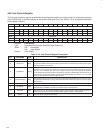
21 cycle64Seconds RSCU Indicates that the 7
th
bit of the cycle second counter has changed.
20 cycleSynch RSCU
Indicates that a new isochronous cycle has started. This bit is set when the low order bit of the cycle
count toggles.
19 phy RSCU Indicates that the PHY requests an interrupt through a status transfer.
18 RSVD R Reserved. Bit 18 returns 0 when read.