


4–24
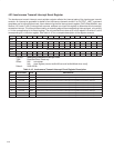
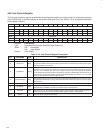
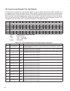
4.28 Link Control Register
The link control set/clear register provides the control flags that enable and configure the link core protocol portions
of the TSB12LV26. It contains controls for the receiver and cycle timer. See Table 4–19 for a complete description
of the register contents.
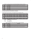
Bit 31 30 29 28 27 26 25 24 23 22 21 20 19 18 17 16
Name Link control
Type R R R R R R R R R RSC RSCU RSC R R R R
Default 0 0 0 0 0 0 0 0 0 X X X 0 0 0 0
Bit 15 14 13 12 11 10 9 8 7 6 5 4 3 2 1 0
Name Link control
Type R R R R R RSC RSC R R R R R R R R R
Default 0 0 0 0 0 X X 0 0 0 0 0 0 0 0 0
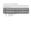
Register: Link control
Type: Read/Set/Clear/Update, Read/Set/Clear, Read-only
Offset: E0h set register
E4h clear register
Default: 00X0 0X00h
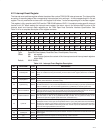
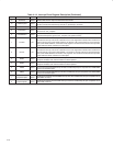
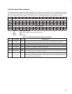
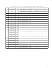
Table 4–19. Link Control Register Description
BIT FIELD NAME TYPE DESCRIPTION
31–23 RSVD R Reserved. Bits 31–23 return 0s when read.
22 cycleSource RSC
When this bit is set, the cycle timer uses an external source (CYCLEIN) to determine when to roll over
the cycle timer. When this bit is cleared, the cycle timer rolls over when the timer reaches 3072 cycles
of the 24.576-MHz clock (125 µs).
21 cycleMaster RSCU
When this bit is set, and the PHY has notified the TSB12LV26 that the PHY is root, the TSB12LV26
generates a cycle start packet every time the cycle timer rolls over, based on the setting of bit 22.
When this bit is cleared, the OHCI-Lynx accepts received cycle start packets to maintain
synchronization with the node which is sending them. This bit is automatically cleared when bit 25
(cycleTooLong) of the interrupt event register (OHCI offset 80h/84h, see Section 4.21) is set and
cannot be set until bit 25 (cycleTooLong) is cleared.
20 CycleTimerEnable RSC
When this bit is set, the cycle timer offset counts cycles of the 24.576-MHz clock and rolls over at the
appropriate time based on the settings of the above bits. When this bit is cleared, the cycle timer offset
does not count.
19–11 RSVD R Reserved. Bits 19–11 return 0s when read.
10 RcvPhyPkt RSC
When this bit is set, the receiver accepts incoming PHY packets into the AR request context if the AR
request context is enabled. This does not control receipt of self-ID packets.
9 RcvSelfID RSC
When this bit is set, the receiver accepts incoming self-ID packets. Before setting this bit to 1,
software must ensure that the self-ID buffer pointer register contains a valid address.
8–0 RSVD R Reserved. Bits 8–0 return 0s when read.