Radio Calibration Test
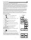
The radio calibration test enables the LTC to generate three different radio test patterns for use in radio
network communications setup. If a radio is not connected, no indication is seen on the TM. The test
patterns can be monitored by connecting an oscilloscope or headphones to the modem 2-wire connector.
To Perform Radio Calibration Test:
1.
Turn off power to controller at power supply switch.
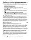
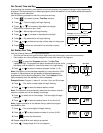
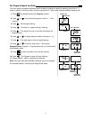
2. Press and hold key while switching on the power. Continue holding down the key for 5 seconds.
The left display will show
CAL.
3. Wait 30 seconds
• Press – A 1200 Hz test pattern will be generated for 30 seconds.
• Press – A 2200 Hz test pattern will be generated for 30 seconds.
• Press – An alternating 1200/2200 Hz test pattern will be generated for 30 seconds.
4. Press to exit Radio Calibration Test mode.
Link Monitor
Link Monitor enables any satellite communicating with the central to review the communications link status
of all satellites within the network. During Link Monitor operation, the central continuously polls the network
satellites in numerical sequence and rapidly displays the addresses accompanied by an audible “beep”. If a
satellite does not respond to the central during the polling process, the satellite address remains displayed
for two seconds and is accompanied by two additional beeps. After all satellites have been polled, the last
satellite address in numerical sequence remains displayed for ten seconds. The polling sequence is
repeated continuously until the Link Monitor is exited by pressing the Exit/Stop key.
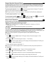
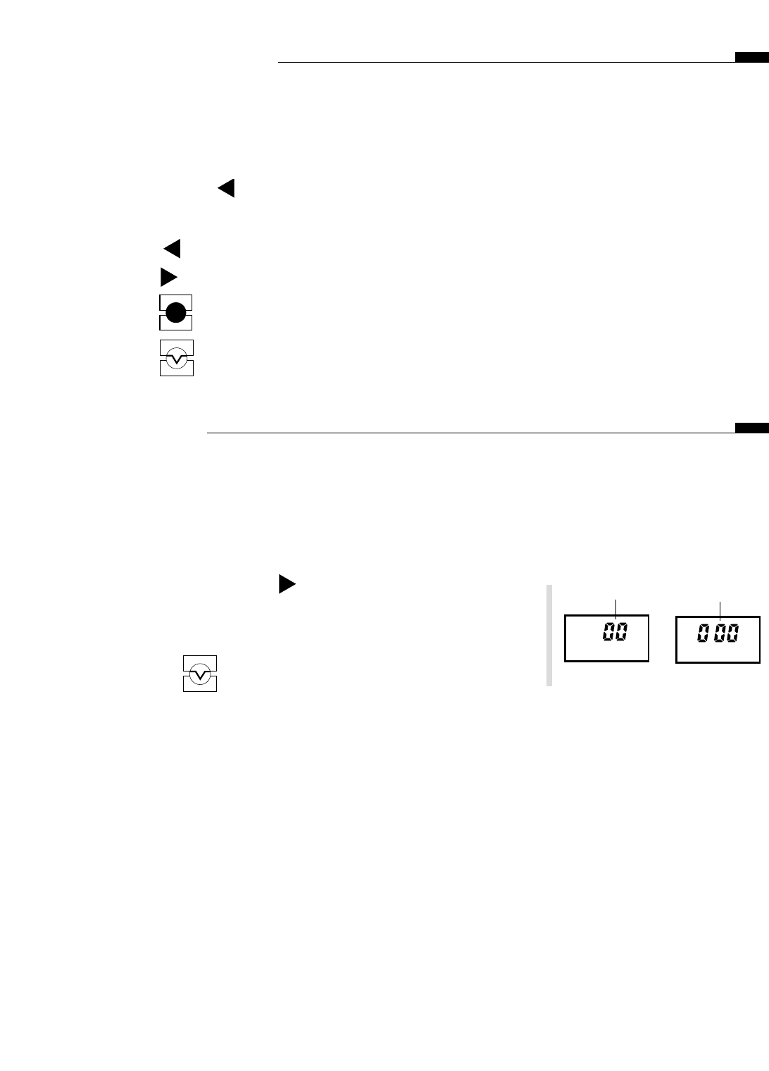
1. Press and hold down the key for five seconds to activate
Link Monitor mode.
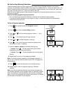
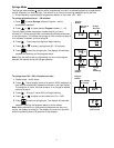
Note: If this satellite is not connected to the network or if the LCM
is not polling,
00 000 will be displayed.
2. Press the key to exit the Link Monitor mode.
EXIT
STOP
EXIT
STOP
ENTER
START
15
Group #
Satellite #


