


4 Replacement Procedures
4-28 Minnesota 10A/10AG Series Maintenance Manual
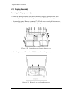
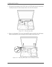
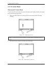
5. Disconnect the microphone cable, WLAN cable, and LVDS cable from the system board.
Carefully disconnect all cables and place them to the side of the notebook.
Figure 4-29 Disconnecting cables
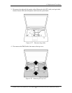
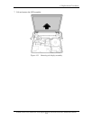
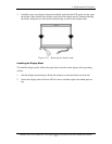
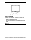
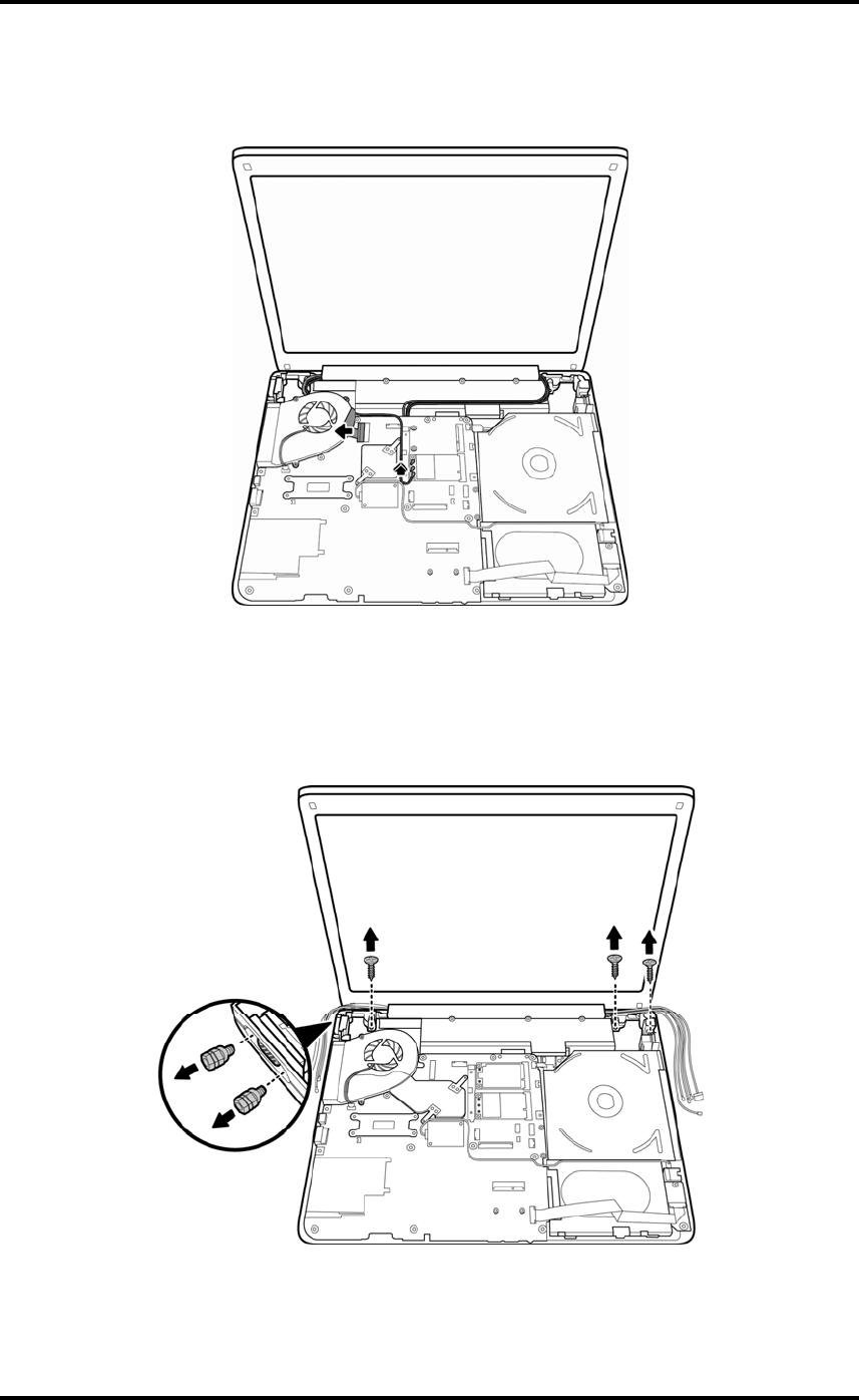
6. Remove two hexagonal VGA screws from the CRT module on the left side of the laptop.
Remove three M2.5x6 screws securing the LCD assembly to the bottom cover.
Figure 4-30 Removing CRT module screws and display assembly