4 Replacement Procedures
4-30 Minnesota 10A/10AG Series Maintenance Manual
Installing the Display Assembly
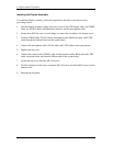
To install the display assembly, follow the steps below and refer to the figures in the
preceding section.
1. Seat the display assembly, taking care not to crush to the LCD display cable, the CMOS
cable, the WLAN cables, the Bluetooth connector, and the microphone cable.
2. Secure three M2.5x6 screws at each hinge to connect the assembly to the bottom cover.
3. Feed the CMOS cable, WLAN cables, microphone cable, Bluetooth cable, and LVDS
cable through the indented track on the system board.
4. Connect the microphone cable, WLAN cable, and LVDS cable to the system board.
5. Replace the top cover.
6. Connect the camera cable (CMOS), right and left speaker cables, Bluetooth cable, FPC
cable, touch pad cable, and function button cable to the system board.
7. Secure the top cover with four M2.5x8 screws.
8. Turn the laptop over and secure seventeen M2.5x8 screws and three M2x3 screws on the
bottom cover.
9. Reinstall the keyboard.


