


T
HE
G
RAND
T
OUR
2-7
Underside
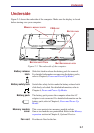
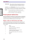
Figure 2-5 shows the underside of the computer. Make sure the display is closed
before turning over your computer.
Figure 2-5 The underside of the computer
Battery release Slide this latch to release the battery pack for removal.
latch For detailed information on removing the battery packs,
refer to Chapter 6,
Power and Power-Up Modes.
Battery safety lock Switch this safety lock to make the battery release latch
slide freely or locked. For detailed information, refer to
Chapter 6,
Power and Power-Up Modes.
Battery pack The battery pack powers the computer when the AC
adaptor is not connected. For detailed information on the
battery pack, refer to Chapter 6,
Power and Power-Up
Modes
.
Memory module This cover protects two memory module sockets
cover One or two modules are preinstalled. Refer to the Memory
expansion
section in Chapter 8, Optional Devices.
Fan vent Provides air flow for the fan.
Underside
B
ATTERY
PACK
B
ATTERY
RELEASE
LATCH
M
EMORY
MODULE
COVER
FAN
VENT
B
ATTERY
SAFETY
LOCK