


2. PRINTER SETUP
ENGLISH VERSION EO1-33028
2.2 Procedure before Operation
E2- 2
2.2 Procedure before
Operation
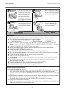
This section describes the outline of the printer setup.
1.
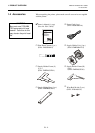
Unpack the accessories and printer from the box.
2.
Refer to Safety Precautions and printer in this manual and set up the
printer at a proper location.
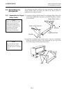
3.
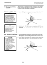
Assemble the Supply Holder Frame and attach the assembled Supply
Holder Frame to the rear of the printer. (Refer to Section 2.3.)
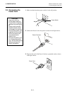
4.
The host computer must have a serial port or Centronics parallel port.
(Refer to Section 2.4.)
5.
Be sure to insert the power cord plug into an AC outlet. (Refer to
Section 2.5.)
6.
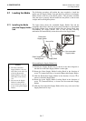
Load the media roll onto the Supply Holder Unit and set it on the
Supply Holder Frame. (Refer to Section 2.7.)
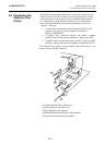
7.
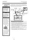
Adjust the position of the Feed Gap Sensor or Black Mark Sensor
depending on the media being used. (Refer to Section 2.8.)
8.
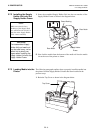
Load the ribbon into the Print Head Block. (Refer to Section 2.9.)
9.
Turn the Power ON. (Refer to Section 2.6.)
10.
Perform a test print. (Refer to Section 2.11.)
11.
Install the Printer Drivers. (Refer to Section 3.)
NOTE:
Use of Windows Driver
allows you to issue media on
the B-852 printer in place of
a general laser printer from
Windows application.
I
nstalling the optional PCL5
interface board in the B-852
p
rinter allows use of the
drivers which support the
PCL5.
The printer can also be
controlled with its own
p
rogramming commands.
Please contact your
TOSHIBA TEC reseller for
the Interface/Communication
M
anual.
NOTE:
To communicate with the
host computer, either an RS-
232C cable or Centronics
cable is required.
(1) RS-232C cable: 9 pins
(2) Centronics cable: 36 pins
(3) Expansion I/O cable: 24
p
ins (Option)