


© 2003 - 2008 TOSHIBA TEC CORPORATION All rights reserved GD-1150/1151/1200/1201/1160/1260
ELECTRICAL CIRCUITS
4 - 5
4
4.2 Description of Circuits
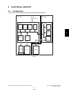
4.2.1 Configuration
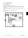
This section describes the function of each circuit.
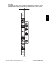
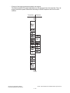
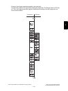
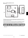
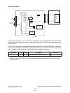
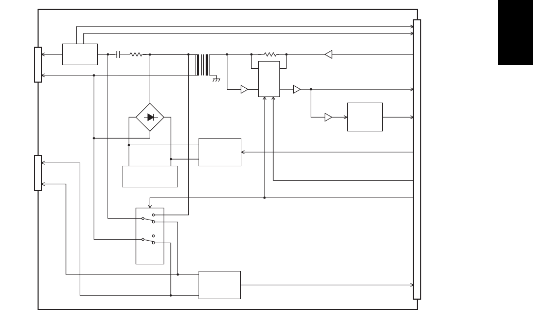
The NCU board consists of the transformer, relay, analog switch and other peripheral devices. It con-
trols switching of the line path, generates the dial pulses, detects the line current and ring signal, and
monitors the line.
The NCU board is connected to CN501 on the FAX board. It can be also connected optionally to
CN502.
The description in this section is based on the NCU board for Line 1.
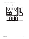
NA/TW models
Fig. 4-5
0
1
0
1
IC53
IC52
T1
RLY2
CML relay
CNG signal
detection
circuit
Line
External
telephone
CN10CN11
CN9
CML
ANSDET
TXOUT
RXIN
REVB
REVA
CI
LD
a2
b2
Lb
La
NCU board
Line current
detection
circuit
IC51
Analog
switch
IC53
IC52
AG
Ring signal
detection
circuit
Dial pulse
generation
circuit
DC
consumption
circuit
+
DB1
-
~
~
FAX board
ATT3DB
04/10