


GD-1150/1151/1200/1201/1160/1260 © 2003 - 2008 TOSHIBA TEC CORPORATION All rights reserved
ELECTRICAL CIRCUITS
4 - 10
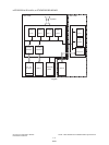
EU/AU/AS/C models
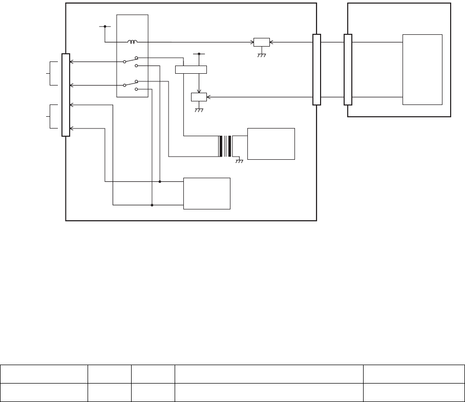
Fig. 4-10
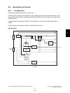
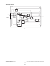
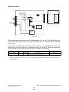
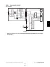
The dial pulse generation circuit consists of the photocoupler (IC1), the ASIC (IC29 [IC26]) on the FAX
board and the other peripheral devices. It generates the dial pulses in the FAX transmission and dialing
to the outside.
The ASIC makes the CML1 signal become HIGH to connect the line to the MODEM side. To generate
the dial pulses, the ASIC makes the LD1 signal become HIGH to turn ON Q6. This allows the photocou-
pler to come on and the current flows through the line for sending a dial attempt.
* Values in [ ] are for GD-1151/1201 in case that the descriptions vary between GD-1150/1200 and
GD-1151/1201.
Signal Name Type Active Description Destination
LD1 O H Line 1 Dial Pulse Generation Signal Q6
T1
AG
CML1
LD1
3
4
AG
CN3
Lb
La
0
1
0
1
10
8
3
5
1
2
6
4
12
9
4
1
+12V
RLY3
CML relay
4
3
a2
b2
2
5
3
4
21
20
FAX board
NCU board
SG
+5V
External
telephone
Line
IC1
Q6
Q4
CN4
CN501
IC29
[
IC26
]
ASIC
Ring signal
detection
circuit
Line path
switching
circuit
08/03