


GD-1150/1151/1200/1201/1160/1260 © 2003 - 2008 TOSHIBA TEC CORPORATION All rights reserved
ELECTRICAL CIRCUITS
4 - 16
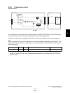
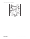
EU/AU/AS/C models
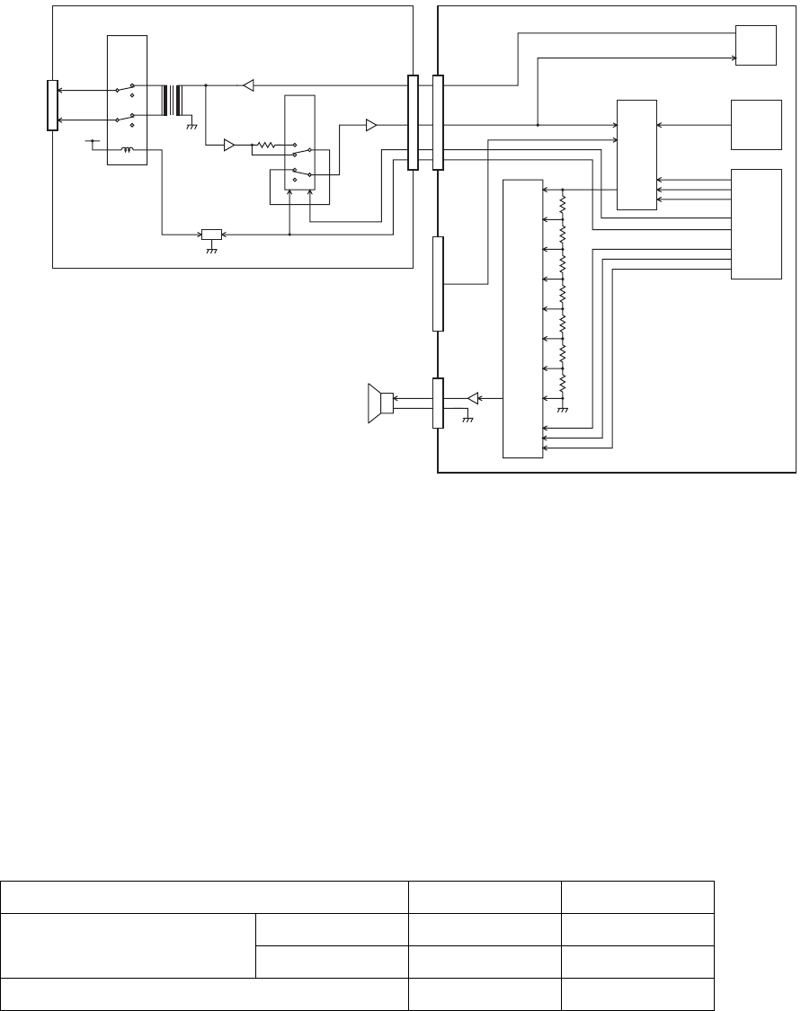
Fig. 4-16
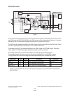
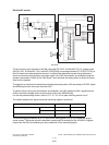
The line monitor circuit consists of the CML relay (NA/TW: RLY2, EU/AU/AS/C: RLY3), analog switch
(NA/TW: IC51, EU/AU/AS/C: IC3), the ASIC (IC29 [IC26]) and analog switches (IC3, IC9 [IC3, IC2]) on
the FAX board, and other peripheral devices. It switches the telephone line path using the analog
switch and monitors the line status and ringer signal in the FAX transmission and reception using the
speaker connected to CN503 on the FAX board. It also switches the analog switch to output a buzzer
tone from the speaker.
The signal to be monitored is selected by switching the analog switch (IC3) according to SP-SEL signal
and MON signal which are output from the ASIC.
To monitor the line during the transmission and reception, the ASIC makes the CML1 signal become
HIGH to switch the analog switch and connect the line to the MODEM side.
For the line path switching control, refer to P. 4-7 "4.2.2 Line path switching control circuit".
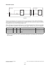
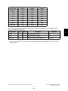
The relation between the signal levels and monitoring signals is as follows.
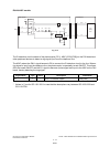
The monitoring signal selected by IC3 is input to the analog switch (IC9 [IC2]) to select the output
sound volume. The sound volume is selected by switching IC8 according to the VOLSEL0-2 signals
output from the ASIC and selecting an input resistance for the monitoring signal.
Monitoring signal SP-SEL MON
LINE Monitor Line 1 LOW HIGH
Line 2 HIGH HIGH
Ringer/Alarm - LOW
NCU board
(
Line1
)
NCU board
(
Line2
)
Speaker
CN4
CN501
IC3
Analog
switch
RLY3
CML relay
CN3
Q4
13
14
15
12
1
5
2
4
11
10
9
IC9
[
IC2
]
Analog
switch
AG
R273
R272
R271
R270
R268
R267
R266
VOLSEL0
VOLSEL1
VOLSEL2
MF-SEL
SP-SEL
6
15
17
18
16
RING
4312
9
10
MON
2611
CML1
ATT3DB1
21
22
IC3
Analog
switch
32
[
9
]
28,29
[
25,26
]
IC29
[
IC26
]
ASIC
IC45
[
IC12
]
CPU
CN502CN503
53
14
2
1
1
2
3
6
2
TXOUT1
RXIN1
1
12
9
10
11
SP+
SP-
IC10
[
IC1
]
SG
FAX board
2RXIN2
14
Lb
La
Line
4
3
13
1
2
15
11 10
T1
IC6
AG
0
1
0
1
8
12
5
9
1
4
0
1
0
1
AG
+12V
IC6
1
276
21
75
3
6
IC4
R11
IC12
[
IC9
]
MODEM
08/03