


© 2003 - 2008 TOSHIBA TEC CORPORATION All rights reserved GD-1150/1151/1200/1201/1160/1260
ELECTRICAL CIRCUITS
4 - 13
4
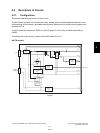
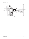
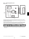
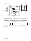
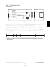
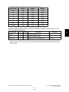
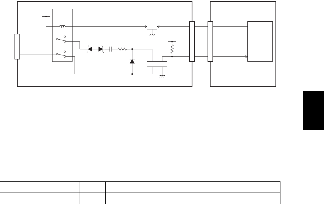
4.2.5 CI detection circuit
NA/TW models
Fig. 4-13
The CI detection circuit consists of the photocoupler (PC2), ASIC (IC29 [IC26]) on the FAX board and
the other peripheral devices to detect a ring signal input from the telephone line.
The ASIC makes the CML1 signal become LOW to connect the CI detection circuit to the telephone
line.
When a ring signal is input from the telephone line, the photocoupler is repeatedly turned ON/OFF. This
allows the CI1 signal to become a pulse signal and input to the ASIC on the FAX board, thereby detect-
ing the ring signal.
* Values in [ ] are for GD-1151/1201 in case that the descriptions vary between GD-1150/1200 and
GD-1151/1201.
Signal Name Type Active Description Destination
CI1 I - Line 1 CI Detect Signal IC29 [IC26]
CN10
Lb
La
Line
0
1
0
1
3
10
12
4
9
1
+12V
RLY2
CML relay
CML1
Q51
3
4
3
3
21
417
NCU board
FAX board
IC29
[
IC26
]
ASIC
CI1
17
1
2
4
3
SG
AG
5VPS
R79
CN9
CN501
PC2
ZD3ZD1
C1
R2
D52
08/03