


© 2003 - 2008 TOSHIBA TEC CORPORATION All rights reserved GD-1150/1151/1200/1201/1160/1260
ELECTRICAL CIRCUITS
4 - 11
4
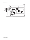
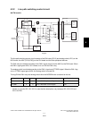
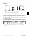
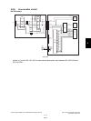
4.2.4 Line current detection circuit
NA/TW models
Fig. 4-11
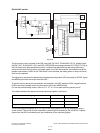
The line current detection circuit consists of the photocoupler (PC3), ASIC (IC29 [IC26]) on the FAX
board and the other peripheral devices. It detects a dial tone and the hook status of the external tele-
phone from the current flowing through the line.
When a dial tone is input from the telephone line, current flows through the line and the photocoupler is
repeatedly turned ON/OFF. This allows the REVA1 and REVB1 to be the pulse signals and input to the
ASIC, then the dial tone is detected.
When the handset is lifted from the external telephone, current also flows through the line and the pho-
tocoupler is turned ON/OFF, then the off-hook state is detected.
* Values in [ ] are for GD-1151/1201 in case that the descriptions vary between GD-1150/1200 and
GD-1151/1201.
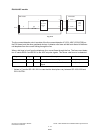
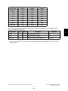
Signal Name Type Active Description Destination
REVA1 I - Line 1 Current Detection Signal IC29 [IC26]
REVB1 I - Line 1 Reverse Current Detection Signal IC29 [IC26]
CN10
Lb
R87
C7
R86
Line
REVA1
REVB1
19
1
2
3
4
6
5
7
8
4
20
19
20
2
3
NCU board FAX board
SG
CN9
CN501
PC3
PC3
IC29
[
IC26
]
ASIC
08/03