


4 Replacement Procedures
4-iv
[CONFIDENTIAL]
Satellite M60 Series Maintenance Manual
Figures
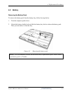
Figure 4-1 Removing the battery pack.................................................................................4-11
Figure 4-2 Pressing the eject button.....................................................................................4-13
Figure 4-3 Installing the PC card.........................................................................................4-14
Figure 4-4 HDD ...................................................................................................................4-15
Figure 4-5 Removing the HDD door ...................................................................................4-16
Figure 4-6 Removing the optical drive module ...................................................................4-18
Figure 4-7 Removing the optical drive bracket ...................................................................4-20
Figure 4-8 Removing the strip cover ...................................................................................4-22
Figure 4-9 Removing the keyboard......................................................................................4-23
Figure 4-10 Disconnecting the keyboard cable......................................................................4-24
Figure 4-11 Removing the wireless LAN card ......................................................................4-25
Figure 4-12 Removing the wireless LAN unit.......................................................................4-26
Figure 4-13 Removing the expansion memory......................................................................4-27
Figure 4-14 Installing the expansion memory .......................................................................4-28
Figure 4-15 Removing the modem module............................................................................4-29
Figure 4-16 Disconnecting the LCD cable ............................................................................4-31
Figure 4-17 Removing the display assembly.........................................................................4-32
Figure 4-18 Removing the top cover-1..................................................................................4-34
Figure 4-19 Removing the top cover-2..................................................................................4-35
Figure 4-20 Removing the TouchPad ....................................................................................4-37
Figure 4-21 Removing the speakers.......................................................................................4-39
Figure 4-22 Removing the system board ...............................................................................4-41
Figure 4-23 Removing the hexagonal screws........................................................................4-41
Figure 4-24 Removing the hexagonal screws........................................................................4-43
Figure 4-25 Removing the CPU.............................................................................................4-44
Figure 4-26 Removing the display mask ...............................................................................4-46
Figure 4-27 Removing the LCD module-1 ............................................................................4-48
Figure 4-28 Removing the FL inverter board........................................................................4-51