


TL-WR542G 54M Wireless Router User Guide
Built-in NAT and DHCP server supporting static IP address distributing
Supports Virtual Server, Port Triggering, and DMZ host
Built-in firewall supporting IP address filtering, Domain Name filtering, and MAC
address filtering
Supports connecting/disconnecting Internet at a specified time of day
Supports access control, allowing parents and network administrators to establish
restricted access policies based on the time of day for children or staff
Supports TCP/IP, PPPoE, DHCP, ICMP, NAT, SNTP
Supports UPnP, Dynamic DNS, Static Routing, VPN pass-through
Supports Traffic Statistics
Supports ICMP-FLOOD, UDP-FLOOD, TCP-SYN-FLOOD filter
Ignores Ping packets from WAN or LAN ports
Supports firmware upgrade
Supports Remote and Web management
Detachable reverse SMA connector antenna
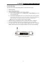
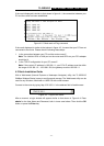
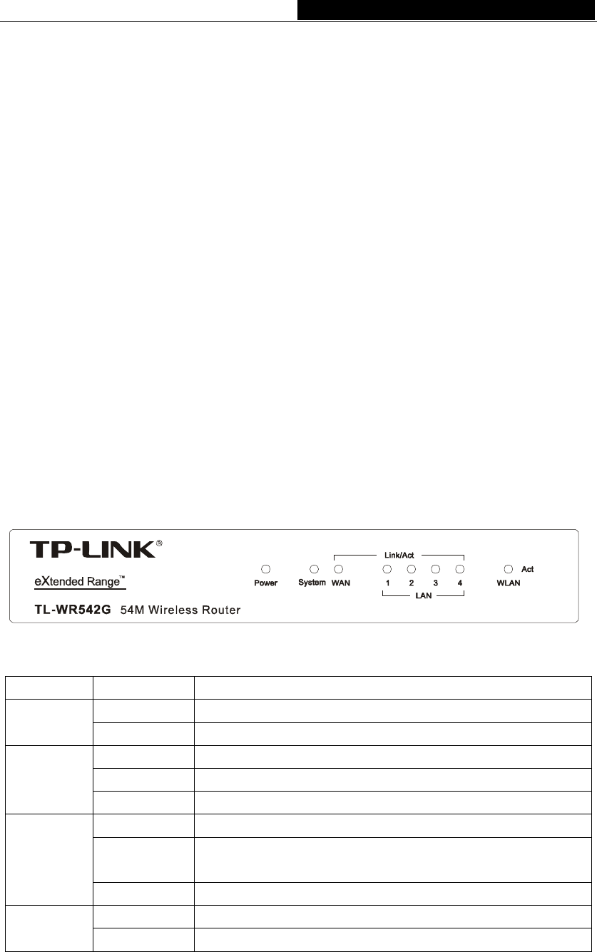
2.3 Panel Layout
2.3.1 The Front Panel
The front panel of the TL-WR542G consists of several LED indicators, which is designed
to indicate connections. Viewed from left to right. Table 2-1 describes the LEDs on the
front panel of the router.
Figure 2-1: Front Panel sketch
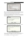
Name Action Description
Not lit No Power
Power
Lit up Power on
Lit up The router is initialising
Flashing The router is working properly
System
Not lit The router has a hardware error
Not lit There is no device linked to the corresponding port
Lit up
There is a device linked to the corresponding port but no
activity
Link/Act
Flashing There is an active device linked to the corresponding port
Not lit The Wireless Radio function is disabled
WLAN
Flashing The Wireless Radio function is enabled
Table 2-1 The LEDs description
- 4 -