


7
6
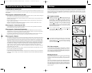
Basic Operation
Buttons (Front Panel)
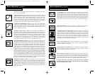
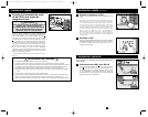
“ON/OFF/STANDBY” Button
When the UPS system is connected to a live AC utility power source, the UPS
System will operate in one of three modes: ON, OFF or STANDBY. Refer to
the chart below for UPS System operating characteristics within each mode.
UPS Charges Battery UPS Supplies Power to Outlets
Mode (when utility is present) (when utility is present or absent*) UPS Displays LEDs
ON Yes Yes Yes (variety of LEDs,
depending on conditions)
OFF No No No
STANDBY Yes No Yes ("BATTERY CHARGE"
LED only)
To place the UPS in the ON mode: First, have a qualified electrician connect
the UPS System to a utility power source as outlined in the Quick Installation
section. Once the utility power source is live, the UPS System will automati-
cally enter STANDBY mode. Press and hold the “ON/OFF/STANDBY” button
for one second** and then release it to switch the UPS System from STAND-
BY mode to ON mode.
OPTIONAL: If the utility power source is not live, you can “cold-start” the
UPS System (i.e.: switch it directly from the OFF mode to the ON mode by
supplying power for a limited time from its batteries*) by pressing and hold-
ing the “ON/OFF/STANDBY” button for one second** and then releasing it.
To place the UPS in the OFF mode: With the UPS System in the ON mode
and receiving utility power, press and hold the “ON/OFF/STANDBY” button
for one second** and then release it to switch the UPS System from ON mode
to STANDBY mode. Switch OFF the facility's circuit breaker which is supply-
ing power to the circuit the UPS System is connected to.
* If batteries are fully charged. ** The alarm will beep once briefly after the interval has passed.
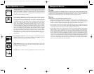
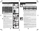
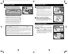
“MUTE/TEST” Button
To Silence (or “Mute”) UPS Alarms: briefly press and release the
MUTE/TEST button.*
To Run a Self-Test: with your UPS connected to a live utility power source and
turned ON, press and hold the MUTE/TEST button for two seconds.* Continue
holding the button until the alarm beeps several times and the UPS performs a
self test. See “Results of a Self-Test” below. Note: you can leave connected equip-
ment on during a self-test. Your UPS, however, will not perform a self-test if the
UPS is not turned on (see “ON/OFF/STANDBY” Button description).
Results of a Self-Test: the test will last approximately 10 seconds as the UPS
switches to battery to test its load capacity and battery charge.
• If the “OUTPUTLOAD LEVEL” LED remains lit red and the alarm continues to
sound after the test, the UPS’s outlets are overloaded. To clear the overload,
unplug some of your equipment and run the self-test repeatedly until the
“OUTPUT LOAD LEVEL” LED is no longer lit red and the alarm is no
longer sounding.
CAUTION! Any overload that is not corrected by the user immediately
following a self-test may cause the UPS to shut down and cease supplying
output power in the event of a blackout or brownout.
• If the “BATTERY WARNING” LED remains lit and the alarm continues to
sound after the test, the UPS batteries need to be recharged or replaced.
Allow the UPS to recharge continuously for 12 hours, and repeat the self-test.
If the LED remains lit, contact Tripp Lite for service. If your UPS requires
battery replacement, visit www.tripplite.com to locate the specific Tripp Lite
replacement battery for your UPS.
* The alarm will beep once briefly after the indicated interval has passed.
4-5
3b
4a
4b
3a
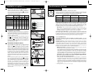
Optional Installation
continued
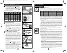
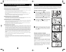
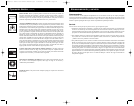
Relay Contact-Closure Connection
Use the included DB9 cable (see ) to connect spe-
cialized electronic equipment to the relay contact-clo-
sure port on your UPS System. See diagram and
chart below to determine signals carried by this port.
Relay Contact Closure Chart
2b
2a
3
4
LINE FAIL
K1 A
LO BATT
K1 0A
1
2
3
4
5
6
7
8
9
OPENS ON LINE FAIL
CLOSES ON LINE FAIL
CLOS ES BELOW LOW BATTERY
TOP OF DUA L
DB9 (J5/J34)
NO TE:
CLOSES BELOW MID BATTER Y
J5
REMOTE CONTACTS
COM
MID BAT
K4 A
CO M
COM
OPENS
BELOW MID BATTERY
RE LAYS SH OW N D E -E NE RG IZ ED
OPENS BELOW LOW BATTERY
2b
2
2a
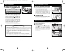
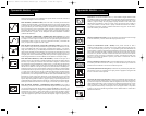
EPO Port Connection
This optional feature is only for those applications
which require connection to a facility’s Emergency
Power Off (EPO) circuit. When the UPS is connected
to this circuit, it enables emergency shutdown of the
UPS’s inverter.
Using the cable provided, connect the EPO port of
your UPS (see ) to a user-supplied normally closed or
normally open switch according to the circuit diagram
(see ). The EPO port is not a phone line surge sup-
pressor; do not connect a phone line to this port.
External Battery Connection
All UPS models come with a robust internal battery
system; select models feature connectors (see ) that
accept optional external battery packs (sold separately
from Tripp Lite) to provide additional runtime. Adding
external batteries will increase recharge time as well as
runtime. See battery pack owner’s manual for complete
installation instructions. Make sure cables are fully
inserted into their connectors. Small sparks may result
during battery connection; this is normal. Do not connect
or disconnect battery packs when the UPS is running
on battery power.
If you connect any
external batteries, set the Battery
Charge Level Switch (see ) to the down position.
This will increase your UPS’s charger output so the addi-
tional batteries charge faster. Note: the switch to the right
of the Battery Charge Level Switch is inactive and will
not affect UPS operation regardless of its position.
CAUTION! DO NOT set the Battery Charge Level Switch to the
down position without an external battery connected. There is a risk
of damaging the UPS’s internal battery system.
4b
4a
3b
3a
Line Fail Mid Battery Low Battery
Indication Indication Indication
UPS Operating Pins 1 Pins 2 Pins 7 Pins 8 Pins 4 Pins 5
Conditions & 6 & 6 & 3 & 3 & 9 & 9
AC Input Voltage OK CLOSED OPEN — — — —
AC Input Out of Range OPEN CLOSED — — — —
Battery More than 3 Min. — — OPEN CLOSED — —
Remaining Charge*
Battery Less than 3 Min. — — CLOSED OPEN — —
Remaining Charge*
Battery More than 2 Min. — — — — OPEN CLOSED
Remaining Charge*
Battery Less than 2 Min. — — — — CLOSED OPEN
Remaining Charge*
Open on Close on Close Open Close Open
Line Line Below Below Below Below
Contact Action Failure Failure Mid Mid Low Mid
Battery Battery Battery Battery Battery
* Times are approximate, at full load.
200505103--Smart 230V Owners Manual.qxd 5/24/2005 11:29 AM Page 6