


9
8
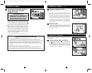
Basic Operation
continued
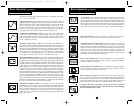
Other UPS Features (Rear Panel)
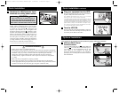
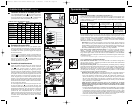
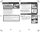
AC Receptacles: Your UPS features IEC320-C13 outlets, and select models
also feature IEC320-C19 outlets. These output receptacles provide your con-
nected equipment with AC line power during normal operation and battery power
during blackouts and brownouts. The UPS protects equipment connected to
these receptacles against damaging surges and line noise. If you have a serial or
USB connection to your UPS, you can remotely reboot connected equipment by
turning the receptacles OFF and ON using Tripp Lite's PowerAlert Software.
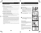
Input Terminal block: Use these terminals to connect the UPS System to
utility power. Unscrew and remove the cover over the block for access.
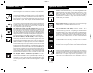
Communications Ports (USB or RS-232): These ports connect your UPS to any
workstation or server. Use with Tripp Lite’s PowerAlert Software and included
cables to enable your computer to automatically save open files and shut down
equipment during a blackout. Also use PowerAlert Software to monitor a wide
variety of AC line power and UPS operating conditions. Consult your
PowerAlert Software manual or contact Tripp Lite Customer Support for more
information. See “USB and RS-232 Serial Communications” in the “Optional
Installation” section for installation instructions.
Relay Contact Interface Port: This female DB9 port sends contact-closure
signals to indicate line-fail and low battery status. See “Optional Installation”
section for installation instructions.
EPO (Emergency Power Off) Port: Your UPS features a EPO port that may
be used to connect the UPS to a contact closure switch to enable emergency
inverter shutdown. See Optional Connection.
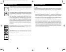
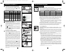
IEC320-C13/230V
IEC320-C19/230V
Charge Rate Setting
(when External Batteries
ar
e not connected)
Charge Rate Setting (when
External Batteries are
connected)
Battery Charge Level Switch: Controls the UPS system’s battery charge rate.
If you connect any external batteries, set the Battery Charge Level Switch to the
down position. This will increase your UPS’s charger output so the additional bat-
teries charge faster. Note: the switch to the right of the Battery Charge Level
Switch is inactive and will not affect UPS operation regardless of its position.
CAUTION! DO NOT set the Battery Charge Level Switch to the down
position without an external battery connected. There is a risk of damaging
the UPS’s internal battery system.
Basic Operation
continued
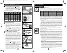
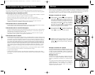
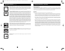
Indicator Lights (Front Panel)
All Indicator Light descriptions apply when the UPS is connected to a live utility
power source and turned ON.
“POWER” LED: this green LED lights continuously when the UPS is ON and
supplying connected equipment with AC power from a utility source. The LED
flashes and an alarm sounds (4 short beeps followed by a pause) to indicate the
UPS is operating from its internal batteries during a blackout or severe
brownout. If the blackout or severe brownout is prolonged, you should save
files and shut down your equipment since internal battery power will eventual-
ly be depleted. See “BATTERY CHARGE” LED description below.
“VOLTAGE CORRECTION” LED: this green LED lights continuously
whenever the UPS is automatically correcting high or low AC voltage on the
utility line without the assistance of battery power. The UPS will also emit a
slight clicking noise. These are normal, automatic operations of the UPS, no
action is required on your part.
“OUTPUT LOAD LEVEL” LED: this multicolored LED indicates the
approximate electrical load of equipment connected to the UPS's AC outlets. It
will turn from green (light load) to yellow (medium load) to red (overload). If
the LED is red (either illuminated continuously or flashing), clear the overload
immediately by unplugging some of your equipment from the outlets until the
LED changes from red to yellow (or green). CAUTION! Any overload that is
not corrected by the user immediately may cause the UPS to shut down and
cease supplying output power in the event of a blackout or brownout.
“BATTERY CHARGE” LED: when the UPS is operating from utility power,
this LED indicates the approximate charge state of the UPS's internal batteries:
red indicates the batteries are beginning to charge; yellow indicates the batteries
are roughly midway through charging; and green indicates the batteries are fully
charged. When the UPS is operating from battery power during a blackout or
severe brownout, this LED indicates the approximate amount of energy (ulti-
mately affecting runtime) which the UPS’s batteries will provide: red indicates
a low level of energy; yellow indicates a medium level of energy; and green
indicates a high level of energy. Since the runtime performance of all UPS bat-
teries will gradually deplete over time, it is recommended that you periodically
perform a self-test (see MUTE/TEST Button description) to determine the energy
level of your UPS batteries BEFORE a blackout or severe brownout occurs.
During a prolonged blackout or severe brownout, you should save files and shut
down your equipment since battery power will eventually be depleted. When the
LED turns red and an alarm sounds continuously, it indicates the UPS's batteries
are nearly out of power and UPS shut down is imminent.
“BATTERY WARNING” LED: this LED lights red and an alarm sounds
intermittently after you complete a self test (See “MUTE/TEST” Button descrip-
tion) to indicate the UPS batteries need to be recharged or replaced. Allow the
UPS to recharge continuously for 12 hours, and repeat the self-test. If the LED
continues to light, contact Tripp Lite for service. If your UPS requires battery
replacement, visit www.tripplite.com to locate the specific Tripp Lite replacement
battery for your UPS.
200505103--Smart 230V Owners Manual.qxd 5/24/2005 11:29 AM Page 8