B022-U08-IP
7
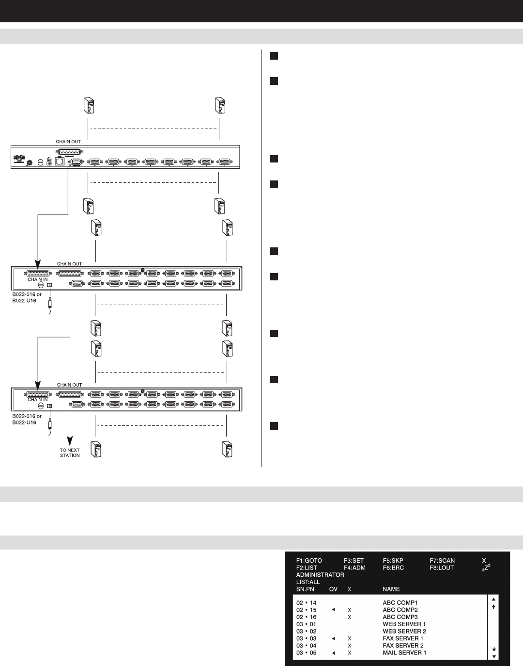
5.5 Multi-Stage Daisy-chain Installation
5.6 Network Setup-IP Address Configuration
5. Installation
(
continued
)
Thenumberofconnectedcomputerscanbeincreasedbydaisy-chaining
additionalB022-016orB022-U16KVMSwitches.Anadditional15
KVMswitchescanbeaddedforatotalof248connectedcomputers.
InordertocongureaxedIPaddress,youwillneedtoaccesstheKVMswitchinoneoffourways;Local Console, IP Installer, Browser or Non-
Browser Clients.
1
PowerOFFallcomputersthatarebeingconnectedtotheKVM
switch.
2
UsingaP772-SeriesDaisy-ChainCable(soldseparately),connect
the Chain OutportonthebackoftherststageKVMtotheChain
InportonthebackofthenextstageKVM.Thedistancebetween
anytwoKVMswitchesinadaisy-chainmustnotexceed49ft.(15
m).ThedistancebetweentherstKVMswitchandthelastKVM
switchinadaisy-chainmustnotexceed328ft.(100m),regardless
ofthenumberofKVMswitchesintheentirechain.
3
Repeatstep2foreachadditionalKVMswitchyouwishtoaddto
theinstallation,withamaximumof16levels.
4
ConnectaP778-SeriesUSB/PS2ComboKVMCableKitbetween
anavailableKVMportandacomputer/server.P778-SeriesCable
KitsallowyoutoconnecttoacomputerwitheitherUSBorPS/2*
keyboard/mouse ports, without the need for separate cables. Note:
The distance between the KVM and the connected computer must
not exceed 33 ft. (10 m).
5
Repeatstep4foreachadditionalcomputer/serveryouwishtoadd
to the installation.
6
ConnecttheincludedexternalpowersupplytotheB022-U08-
IP,andthenplugitintoaTrippLiteSurgeSuppressor,PDUor
UninterruptiblePowerSupply(UPS).TurnontherststageKVM
switch.TheStationIDontheKVM’skeyboardpanelwilldisplay
01.
7
Connect the external power supply included with the next stage
KVMswitchandplugitintoaTrippLiteSurgeSuppressor,PDUor
Uninterruptible Power Supply (UPS). The Station IDontheKVM’s
front panel will display 02.
8
Repeatstep7foreachsubsequentKVMswitchintheinstallation.
Ineachcase,waitforthepreviousKVMswitchesStationIDto
bedisplayedbeforeconnectingthepowercordtothenextKVM
switch.
9
Power ON the connected computers.
*WhenconnectingtocomputersusingthePS/2connectorsofaP778-SeriesCableKit,the
Mouse Sync ModesettingmustbesettoManualinordertoaccessthecomputeroverIP.
If Mouse Sync Mode is set to Automatic, you will not have mouse functionality when
accessing that computer over IP. This setting is set to Manual by default.
5.6.1 Local Console
Note: The local console OSD only allows you to configure IPv4 network
settings. For IPv6, access the Web Management Interface or Remote
Session OSD.
1. WhenaccessingtheKVMswitchforthersttime,apromptwill
appear asking for a Username and Password. The default Username
is administrator, and the default Password is password. For
security purposes, it is strongly recommended that you change the
username and password on this account to something unique. When
youhaveenteredyourusernameandpassword,theOSDwillappear
with the following page displayed.
