http://www.tyan.com
18
Chapter 2
Board Installation
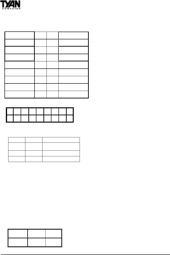
1-B. Panel Connector Settings (Jumper J16)
Power LED:
For 2-pin: bicolor/single
color - Use pins 2-4
1-C. BUS Speed Settings (FS0, FS1)
1-D. Speaker Connector (Jumper J12)
The speaker should be connected to pins 1-4 of jumper J12. As default,
pins 3-4 of jumper J12 are connected to the internal buzzer.
1-E. Wake-On LAN (CON3)
1-F. Wake-On Ring (CON2)
1-G. Clear CMOS and Reset Password (Jumper JP2)
tluafeDteseR
2PJ
2-13-2
HDD LED+ 12 Power LED
HDD LED- 34 Sleep LED
Ground 56Power On/Off
Reset 78 Ground
IR +5V 910 No Connect
IR Receive 11 12 Power +5V
Ground 13 14 No Connect
IR Transmit 15 16 No connect
No Connect 17 18 No Connect
Top
Bottom
J16
1 3 5 7 911131517
2 4 6 8 10 12 14 16 18
0SF1SF
ffOffO
zhM331tceteD-otuA/otuA
UPCaiv
ffOnO zhM001
nOnO zhM66
133Mhz BUS Speed can only
be set if the CPU supports a
133 Mhz Front Side BUS.


