


11
QUICK START
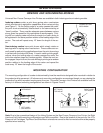
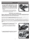
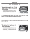
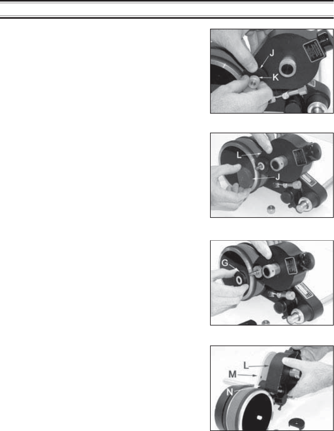
6 -Carefully pull the Inking System Cover “L” directly away
from the Inking System Baseplate “M”. Do not let the cover
drag across the surface of the Transfer Roller “N”.
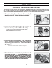
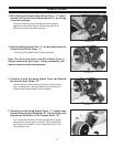
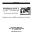
3 -While holding the Knurled Drive Wheel Cover “J” in place,
remove the Knurled Cover Retaining Knob “K” by turning
it counter-clockwise.
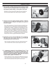
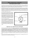
4 -Hold the Inking System Cover “L” in place and remove the
Knurled Drive Wheel Cover “J”.
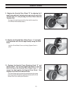
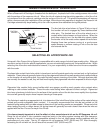
5 -Continue to hold the Inking System Cover and Remove
the Knurled Drive Wheel “G”.
FIGURE 15
FIGURE 16
FIGURE 17
FIGURE 18
The Cover Retaining Knob holds the entire inking system
together and other parts may fall free from the coder if not
held securely when this knob is removed.
Note: The flat on the side of the Drive Wheel Cover is
aligned towards the print drum. During reassembly, this
must be replaced in the same position.
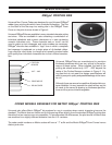
The Knurled Drive Wheel rests on top of the Transfer Roller
and is installed over 3 stainless steel drive pins which pro-
trude through 3 mating holes in the Drive Wheel.
The Transfer Roll Surface is a finely engraved Delrin plastic
material which can be easily scratched. When assembled,
the Transfer Roll resides in a very close fitting cavity in the
Inking System Cover.
The Knurled Drive Wheel Cover is very loose fitting.