


31
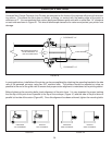
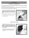
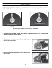
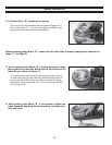
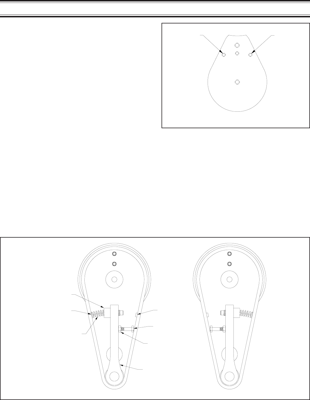
1- Loosen the Lock Nut and screw the Adjusting Bolt in to relieve the spring pressure (Figure 56).
2- Remove the spring by lifting the end off the Locating Button.
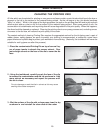
3- Remove the Adjusting Bolt and replace it on the opposite side of the Tension Arm.
4- Remove the Spring Cup and replace it on the opposite side of the Tension Arm.
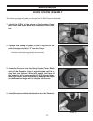
5- Replace the Spring by inserting one end into the Spring Cup and lifting the other end over the
Locating Button.
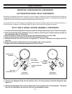
6- Readjust the position of the Adjusting Bolt to center the Tension Arm between the sides of the coder
base plate. Snug the Lock Nut against the Tension Arm to prevent movement from conveyor vibra-
tion.
TENSION ARM ASSEMBLY CONVERSION
FIGURE 56
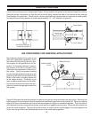
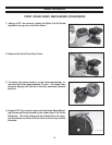
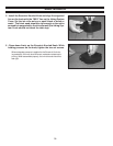
10 -Reinstall the Inking System Assembly and
adjust as explained on Page 9 - Installing the
Inking System Assembly.
SPRING CUP
LOCATING
BUTTON
SPRING
LOCATING
BUTTON
ADJUSTING BOLT
LOCK NUT
TENSION ARM
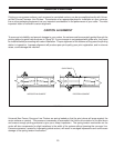
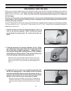
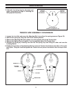
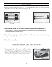
MAINTENANCE
SET SCREW
POSITION
FOR RIGHT
HAND MOUNT
SET SCREW
POSITION
FOR LEFT
HAND MOUNT
BOTTOM VIEW OF
INKING SYSTEM BASEPLATE
FIGURE 55