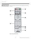
Controls and Functions
Vidikron Vision 30 Series Owner’s Operating Manual 7
PRE
L
IMINAR
Y
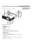
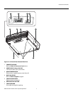
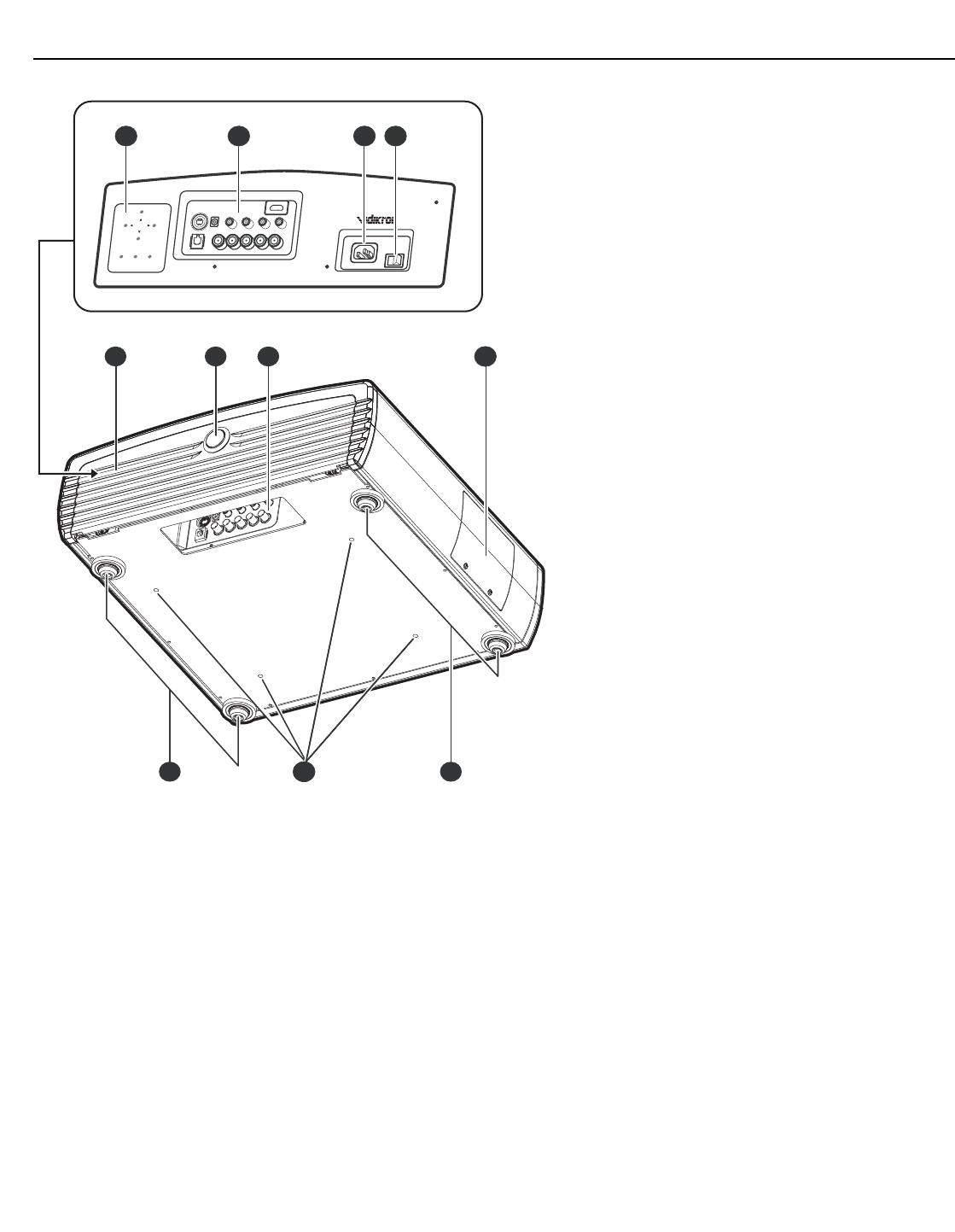
Figure 2-2. Vision 30 Rear/Bottom/Side View
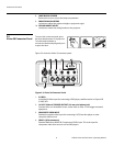
1. CONNECTOR PANEL
Refer to Vision 30 Connector Panel, below.
2. POWER INPUT (100 to 240 VAC)
Connect the Vision 30 to power here.
3. MAIN POWER SWITCH
Disconnects or applies power to the Vision 30.
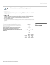
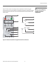
4. BUILT-IN KEYPAD
Refer to Built-In Keypad on page 9.
5. CABLE ACCESS DOOR
Open to access connectors.
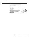
6. DOOR RELEASE BUTTON
7. CABLE OPENING
Pass cables through this opening.
MEMORY
MEMORY
AUTO
AUTO
POWER
POWER
MENU
/EXIT
MENU
/EXIT
SOURCE
/ENTER
SOURCE
/ENTER
1 2 3 4
8765
9 10 9


