VXI Technology, Inc.
56 SM8000 Series Programming
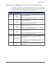
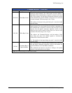
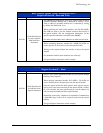
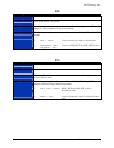
Relay (Optical Module’s Data (Attenuation Level))
Register 02 thru 08 – Read and Write
ADDR
Plug-In LA+0x002 – 0x008
The SM8000 can alternatively drive up to 4 optical multi switch or
attenuator modules. Module one is addressed by writing a 16-bit
word to address LA+0x002; module two is controlled by writing
to address LA+0x004 and so on.
When controlling the multi switch modules, data bits D4 (MSB)-
D0 (LSB) are used to pass the channel selection data directly to
the optical module. See the configuration information for the
specific optical module that is installed in the SM8000.
For multi switch modules, these addresses are both read and write.
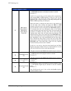
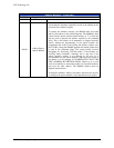
D15-D0
16 Bit Data Word to
be sent to Optical
Multi Switch or
Attenuator
When controlling attenuator modules D15 (MSB)-D0 (LSB) are
used to pass the 16 bit control word to the optical module.
Writing to this register initiates the transfer of data to the optical
module.
For attenuator modules, these addresses are write only.
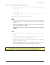
See typical Optical Attenuator control example.
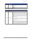
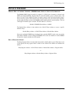
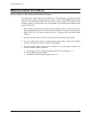
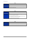
Relay (Optical Module’s Data (Attenuation Level))
Register 0A thru 0C – Read
ADDR
Plug-In LA+0x00A – 0x00C
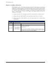
D15-D0
16 Bit Data Word to
be read back from
Optical Attenuator
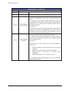
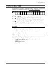
Queries of the optical attenuator module may be acquired through
reading of these registers.
When querying attenuator modules D15 (MSB) - D0 (LSB) are
used to read the three 8-bit data bytes from the optical module.
Once the optical module has been queried, these registers may be
read to receive the data retrieved from the optical module. Address
0C will read back the most significant byte, and the address 0A
will read back the middle and least significant byte.
Depending on the query command (see Attenuator Command Set)
a predefined byte count will be received back from the optical
module.
See typical Optical Attenuator control example.


