


VXI Technology, Inc.
60 SM8000 Series Programming
COMMAND REGISTER
The following register addressing is based on the Phillips I
2
C specification. For more detailed
information, please refer to Phillips document titled The I
2
C Bus and How To Use It.
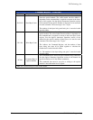
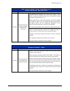
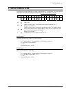
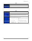
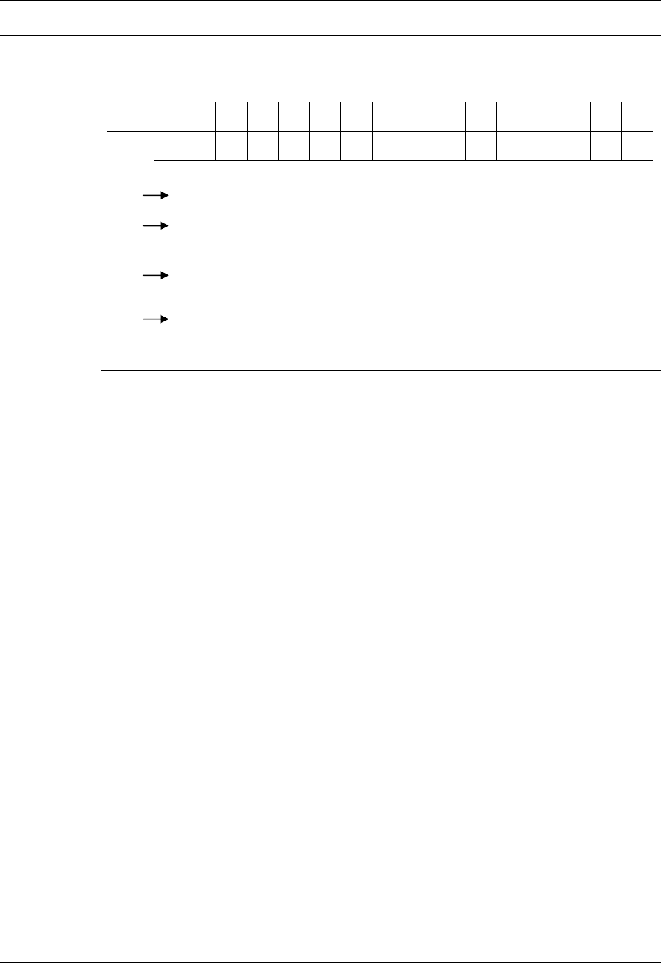
Bits
15 14 13 12 11 10 9 8 7 6 5 4 3 2 1 0
D R R R D W W W C C C C C C C C
D
Don’t Care
R
Number of data bytes to be read back from the optical module plus 1.
Range: 8 to 0 decimal.
W
Number of data bytes to be written to the optical module. This number should
include the Address and Command Bytes, along with the number of data
bytes that are to be written to the module.
Range: 8 to 0 decimal.
C
Command Byte. See Attenuator Command Set.
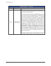
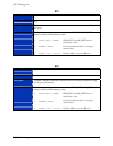
Write Example
Command optical module to Move-To-Absolute-Step:
W = 1 Address Byte + 1 Command Byte + 2 Data Bytes to Send = 4
R = 0 (no data is expected back)
C = 30h
Command Register = 0430h
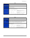
Read Example
Query optical module’s Current Step:
W = 1 Address Byte + 1 Command Byte + 0 Data Bytes to Send = 2
R = 2 Data Bytes to Read Back + 1 = 3
C = 31h
Command Register = 3231h