VXI Technology, Inc.
SM8000 Series Programming 57
PROGRAMMING EXAMPLES
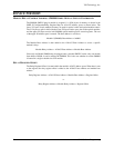
TYPICAL OPTICAL MULTI-SWITCH CONTROL EXAMPLE
The optical multi-switch modules are controlled via a 5-bit parallel port. To select the optical
switch, the binary number corresponding to the switch is written to the SM8000 optical switch
controller. The multi-switch modules may be located at register locations 02 through 08. The
following sequence could be used to select switch number 5, on the multi-switch module located
at register location 02:
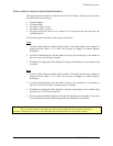
1. Write a 0004h to location 02h. Calculate the relay register address as shown above in the
Relay Register Offset section, where the module relay address is always 0, and the register
offset is 02h. This will select the optical path that is associated with optical multi-switch
number 5.
2. Once the switch has settled, a read of location 02h would confirm the value of 0004h.
3. To set the multi switch module to another desired switch setting, simply write the BCD
number corresponding to the switch required to the SM8000.
4. To reset the multi switch to the power-on condition, i.e. no optical paths connected, the
following sequence must be performed:
a) Set the optical module’s corresponding Reset Bit in the Control Register to ‘1’.
b) Write a x0h to the optical module.
c) Set the Reset Bit in the Control Register back to “0”.


