


APPENDIX
89
WD SENTINEL DS5100/DS6100
ADMINISTRATOR AND MAINTENANCE GUIDE
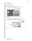
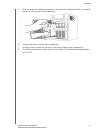
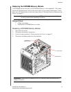
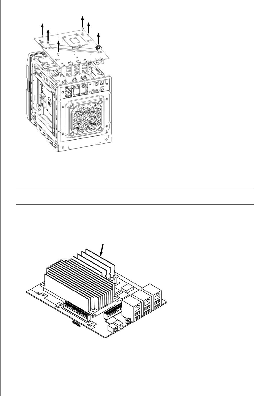
5. On the top of the unit, loosen and remove the six (6) screws holding the PCBA unit in
place.
Figure 7. Remove screws from PCBA unit
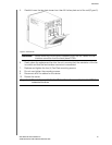
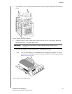
6. Carefully lift the PCBA up and away from the rest of the unit, then gently place the
flipped assembly on a stable flat surface.
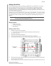
7. Remove and replace or add additional 2PL-SODIMM module(s).
Note: This unit uses memory in coordinated pairs and are color-coded. For a list of
valid memory configurations, search for Answer ID 9999 in the WD Knowledge Base
at http://support.wd.com.
Figure 8. Replace 4PL-SODIMM module
WARNING! Ensure that the connector clears the plate when removing the
assembly.