


FORMS LAYOUT CONSIDERATIONS
XEROX DOCUPRINT 96/DOCUPRINT 96MX LPS FORMS CREATION GUIDE 5-3
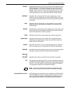
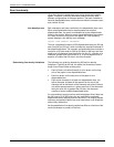
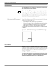
In addition, it is possible to have the line table show more than one
line passing in the same direction through a given coordinate. For
example, draw three lines, each of which is five units in length (0 to
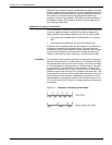
5, 10 to 15, and 20 to 25). Then draw two lines, each of which is nine
units in length (3 to 12 and 13 to 22). The result is a single visual line
for which FDL has three entries in the line table (0 to 12, 10 to 22, and
20 to 25). Figure 5-2 shows lines entered in unintended locations.
Figure 5-2. Lines entered in unintended locations
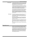
These two examples of awkwardly entering lines into the line table
result in lines that are visually contiguous but not logically
contiguous. As indicated in the subsequent sections that describe
problems with boxes, such conditions can result in a situation where
FDL is unable to find a box or creates a box that has one or both of
its dimensions equal to zero.
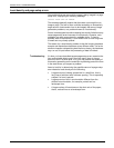
Suggested techniques for
entering lines
The suggested technique for entering lines is to draw the longest
possible logical line first, then draw any shorter elements. If the
logical line consists of different types of lines (for example, solid and
dotted), draw a SOLID 0 line first extending over the full range of the
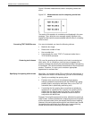
logical line. For instance, the previously cited example of five line
segments of five units each might have consisted of alternating solid
and dotted lines. In that case, the most reasonable method of
specifying the total line would be as follows:
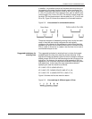
AT 0 LINE 0 TO 25 USING SOLID 0;
AT 0 LINE 0 TO 5 USING SOLID 2 AND AT 10, 20;
AT 0 LINE 5 TO 10 USING DOTTED 1 AND AT 15;
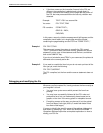
Figure 5-3 shows the line that would be drawn.
Figure 5-3. Line made up of different types of lines