


E-9
CONNECTIONS
English
DVI
INPUT B
RGB/YP
B
P
R
/YC
B
C
R
D4 VIDEO G/Y B/P
B
/C
B
R/P
R
/C
R
INPUT A
HD/SYNC VD
OUT IN
REMOTE
RS-232C
S-VIDEO VIDEO
TRIGGER OUT
G
/
YR
/
P
R
/
C
R
B
/
P
B
/
C
B
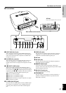
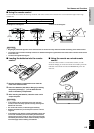
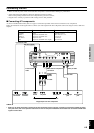
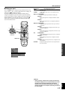
◆ Note ◆
• Make sure to match the Y/PB/PR or Y/CB/CR of the A/V component and this unit when connecting a component to INPUT A compo-
nent jacks. Also, refer to the operation instructions for the A/V component. HD/SYNC and VD need to be connected for RGB video
signals in some cases.
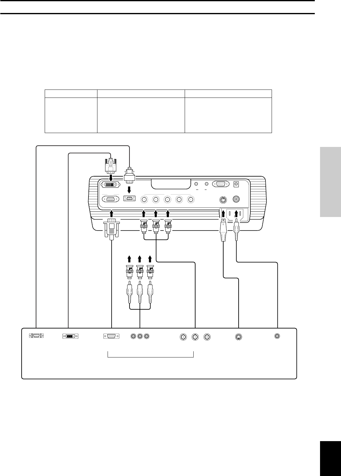
Connecting the unit
• Make sure that the power of this unit and all other components is turned off before making any connections.
• Some components have different connection methods and connector names.
Refer to the operating instructions for each component that you wish to connect.
• Plug the unit in correctly to prevent it from creating noise or other problems.
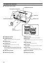
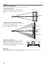
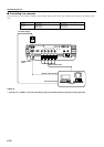
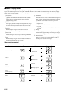
■ Connecting A/V components
As shown in the illustration below, there are 5 types of connections provided on this unit for connection to A/V components.
Follow the instructions on the figure below to connect A/V video outputs from other components to this unit using the correct cables and
adapters.
D connector cable
D-sub monitor
cable
BNC cable for component
connection
Pin/BNC
adapters
Pin cable
Video pin cable
S video cable
D1—4 output
connectors
Pin jacksD-sub
Component/RGB video output connectors
Image output from A/ V components
BNC jacks S video output
jack
Video output
jack
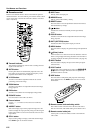
Input
VIDEO
S-VIDEO
INPUT A
INPUT B
D4 VIDEO
DVI
Signal type
Composite video
S video
Component video/RGB video
Component video/RGB video
Component video
Component video/RGB video (digital)
Connector type
Pin jack
Mini DIN connector
BNC connector x 3—5
D-sub 15 pin
D connector
DVI connector
DVI cable (digital)
DVI output
connector