


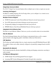

Prestige 128IMH ISDN Modem/ Router/Hub
Hardware Installation and Setup 2-1
Chapter 2
Hardware Installation & Initial Setup
This chapter shows you how to connect the hardware and the initial setup.
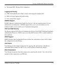
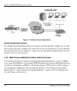
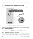
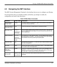
2.1.1 Front Panel LEDS
The LED indicators on the front panel indicate the router/hub functional status of the Prestige.
The following table describes the LED functions:
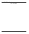
PWR
ISDN LAN PHONE
TST LNK B1 B2 1 2 3 4 1 2
Remote Access Router
Figure 2-1 Front Panel
PWR The PWR (power) LED is on when power is applied to the Prestige.
TST A blinking TST (test) LED indicates the Prestige is functioning properly. A
steady or an off TST indicates malfunction.
ISDN: LNK The LNK (Link) LED is on when the Prestige is connected to an ISDN
switch and the line has been successfully initialized.
ISDN: B1/B2 The B1/B2 LED is on when the corresponding B channel is in use.
LAN: 1 to 4 A steady LED indicates an active station is connected to the corresponding
port. The LED blinks when the connected station is transmitting.
PHONE: 1/2 The LED is on when the device on the corresponding POTS port is in use.
Table 2-1 LED functions