Installing the Switch on a Flat Surface
SecureStack A2 Installation Guide 3-7
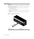
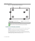
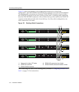
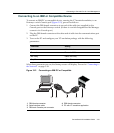
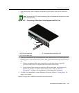
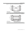
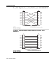
ToremoveaMini‐GBICfroma portslot,referbacktoFigure 3‐1,Figure 3‐2,and
Figure 3‐3,andproceedasfollows:
1. Attachyourantistaticwriststrap(refertotheinstructionsinyourantistaticwrist
strappackage)beforeremovingtheMini‐GBIC.
2. RemovethecablesconnectedtotheMini‐
GBIC.
3. LocatethereleasetabunderthefrontendoftheMini‐GBIC.Forthetypeof
Mini‐GBICshownin:
a. Figure 3‐1,pushdownonthemetalreleasetababovetheconnectorasfarasit
willgotoreleasetheMini‐GBICfromtheportslot.
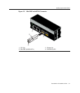
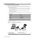
b. Figure 3‐2,
pushinonthereleasetabasfarasitwillgotoreleasetheMini‐GBIC
fromtheportslot.
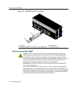
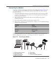
c. Figure 3‐3,pulloutonthereleasetabtoreleasetheMini‐GBICfromtheportslot.
4. GraspthesidesoftheMini‐GBICandpullitstraightoutof
theportslot.
IfstoringorshippingaMini‐GBIC,whichhasafiber‐opticconnector,insertitsprotective
dustcovertoprotecttheendsofthefiber‐opticfibersfromdustorcontamination.
Installing the Switch on a Flat Surface
Wheninstallingtheswitchonaflatsurface,theinstallationoftherubberfeetis
recommendedtopreventtheswitchfromslidingonaflatsurface.Installingtherubber
feetisoptionalifyouareinstallingtheswitchinarack.Toinstalltherubberfeet,proceed
to“Installingthe
RubberFeet”instructionsbelow.Forinstructionstorackmountthe
switch,proceedto“RackMountingtheSwitch”onpage 3‐10.
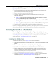
Installing the Rubber Feet
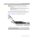
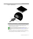
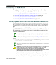
Toinstalltherubberfeet,refertoFigure 3‐4andproceedasfollows:
1. Placetheswitchonitsbackonasturdyflatsurfacetogainaccesstothebottomofthe
chassis.
2. Removethefourrubberfeetfromtheirplasticbagintheshippingbox.
3. Locatethefourmarkedlocationson
thebottomfourcornersofthechassis.
4. Removetheprotectivestripfromthebackofonerubberfootandpositionitona
markedlocationandpressfirmlyintoplace.Repeatthisproceduretoinstallthe
remainingthreerubberfeetintheotherthreelocations.
5. Afterinstallingtherubberfeet,return
theswitchtoitsuprightposition.
6. Proceedto“GuidelinesforFlatSurfaceInstallation”onpage 3 ‐8.Forarackmount
installation,proceedto“RackMountingtheSwitch”onpage 3‐10.