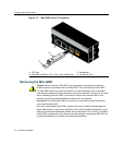
Connecting to the Network
SecureStack A2 Installation Guide 3-25
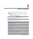
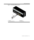
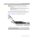
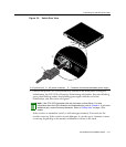
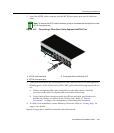
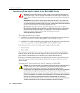
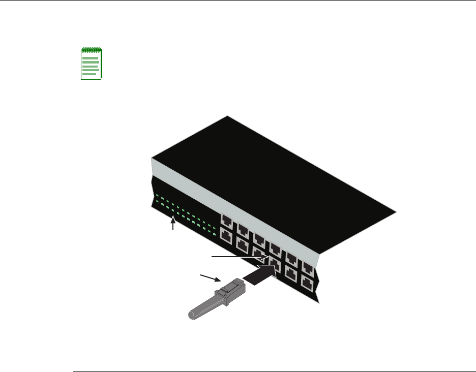
2. InserttheMT‐RJcableconnectorintotheMT‐RJfrontpanelportuntilitclicksinto
place.
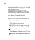
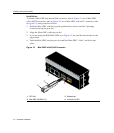
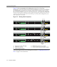
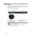
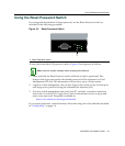
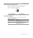
Figure 3-15 Connecting a Fiber-Optic Cable Segment to MT-RJ Port
3. VerifythatalinkexistsbycheckingthattheLi nk/ActivityLEDisON(solidgreenor
blinkinggreen).IftheLink/ActivityLEDisOFF,performthefollowingstepsuntilitis
on:
a. If
thereareseparatefiber‐opticconnectionsontheotherdevice,checkthe
crossoverofthecables.Swapthecableconnectionsifnecessary.
b. VerifythatthefiberconnectionmeetsthedBlossandcablespecificationsfor
multimodecabling,asoutlinedintheCablingGuide.Referto“Related
Documents”onpage xvifor
informationonobtainingthisdocument.
4. Ifalinkisnotestablished,contactEnterasys Networks.Referto“GettingHelp”on
page 1‐6fordetails.
Repeatallstepsaboveuntilallconnectionshavebeenmade.
Note: To remove the MT-RJ cable connector, press on its release tab and pull it out of the
MT-RJ front panel port.
1 MT-RJ cable connector 3 Front panel Port Link/Activity LED
2 MT-RJ front panel port
135791
1
13 1
5
17 19 21 2
3
2468101214 1
6
1
820
2
224
2
81
0
1
246
1
791
13
5
À
Á
Â