Connecting to the Network
SecureStack A2 Installation Guide 3-29
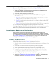
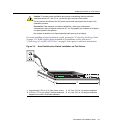
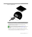
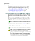
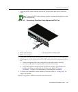
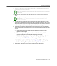
1. RemovetheprotectivecoversfromtheMini‐GBICLCfiber‐opticportandfromthe
connectorsoneachendofthecable.
2. InserttheLCcableconnectorintotheMini‐GBICLCconnectoruntilitclicksinto
place.
3. Plugtheotherendofthecableintotheappropriateportontheother
device.Some
cablesmaybeterminatedattheother endwithtwoseparateconnectors,oneforeach
fiber‐opticstrand.Inthiscase,ensurethatthetransmitfiber‐opticstrandisconnected
tothereceiveportandthereceivefiber‐opticstrandtothetransmitport.
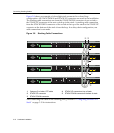
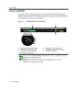
4. Verifythatalinkexists
bycheckingthattheportLink/ActivityLEDison(blinking
greenorsolidgreen).IftheLink/ActivityLEDisoff,performthefollowingstepsuntil
itison:
a. VerifythatthedeviceattheotherendofthesegmentispoweredONand
connectedtothesegment.
b. Ifthereareseparate
fiber‐opticconnectionsontheotherdevice,checkthe
crossoverofthecables.Swapthecableconnectionsifnecessary.
c. Checkthatthefiber‐opticconnectionmeetsthedBlossandcablespecifications
outlinedintheCablingGuideformultimodemodecabling.Toobtainthis
document,referto“RelatedDocuments”on
page xvi.
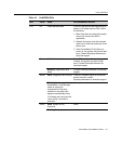
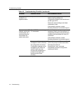
d. Ifalinkhasnotbeenestablished,refertoChapter 4for LEDtroubleshooting
details.Ifaproblempersists,refertoreferto“GettingHelp”onpage 1‐6for
detailsoncontactingEnterasys Networksforsupport.
5. Repeatsteps1through4,above,untilallconnectionshavebeenmade.
Note: Leave the protective covers in place when the connectors are not in use to prevent
contamination.
Note: To remove the LC cable connector, press on its release tab and pull it out of
Mini-GBIC LC connector.