Connecting Stacking Cables
SecureStack A2 Installation Guide 3-11
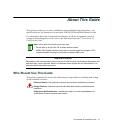
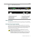
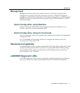
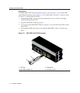
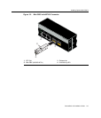
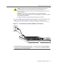
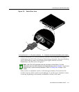
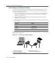
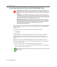
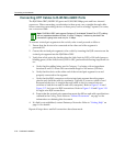
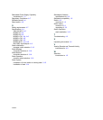
Figure 3-6 Attaching the Rackmount Brackets
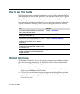
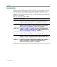
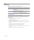
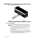
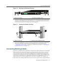
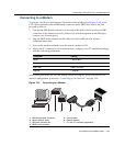
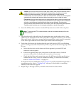
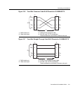
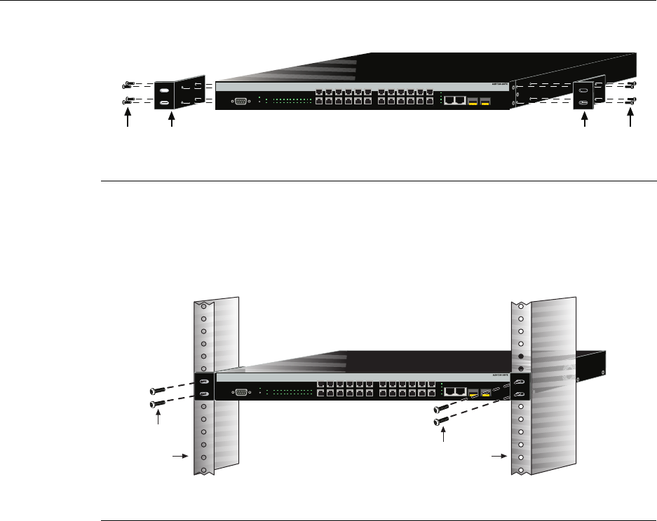
2. Withthemountingbracketsattached,positiontheswitchbetweentheverticalframe
membersofthe19‐inchrackasshowninFigure 3‐7.Thenfastentheswitch securely
totheframeusingfourmountingscrews(usersupplied).
Figure 3-7 Fastening the Switch to the Rack
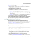
3. Ifyouareinstallingthisswitch inastackedconfiguration,repeatthisprocedure
for
eachswitchuntilallswitcheshavebeeninstalledinthestack,thenproceedto
“ConnectingStackingCables”onpage 3‐11.Otherwise,proceedto“ConnectingAC
andRPS‐SYSPower”onpage 3‐16.
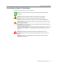
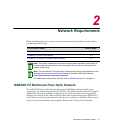
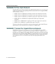
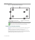
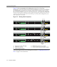
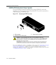
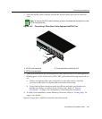
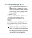
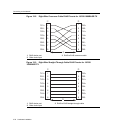
Connecting Stacking Cables
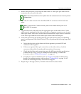
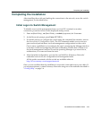
Thestackofswitchescanbeconnectedinaclosedloopordaisychained.Inaclosedloop
alltheswitchesareconnectedinsequenceandthelastswitchinthestackisconnected
backtothefirstswitch.Inadaisychainconfigurationthecablethatwouldreturnthe
connection
backtothefirstswitchinaclosedloopisnotinstalled.Theadvantageofthe
closedloopisredundancy,thisconfigurationeliminatesanysinglepointoffailure.Upto
eightswitchescanbestackedtogetherandconnectedbystandardUTPCategory5or
bettercables.Thestackingcablesallow
theentirestacktooperatewithasingleIPaddress.
1 Rackmount brackets 2 M3x6 mm flathead screws
1 Rails of 19-inch rack 2 Mounting screws (supplied by user)
Á
À
Á
À
Console
CPU
RPS
MGR
1 3 5 7 9 11 13 15 17 19 21 23
24681012141618202224
25
26
27
28
25/Up 26/Down
Stack
27
28
2 8 10 1246
179113 5 13 19 21 2315 17
14 20 22 2416 18
Á
À
Á
À
Console
CPU
RPS
MGR
1 3 5 7 9 11 13 15 17 19 21 23
24681012141618202224
25
26
27
28
25/Up 26/Down
Stack
27
28
2 8 10 1246
179113 5 13 19 21 2315 17
14 20 22 2416 18