10
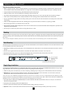
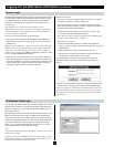
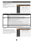
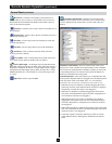
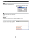
The B064-Series KVM Switches support hot plugging: components can be removed and added back into the installation by unplugging and
replugging their cables from the ports without the need to shut the unit down. The KVM also includes an Adapter ID function that stores the port
settings of the SIU (Port OS, OS Language, etc.), allowing you to switch an SIU and its connected computer to a new port without having to re-
enteritsportsettings.ThesettingsarestoredbySIUonly;therefore,thecorrectsettingswillnottransferifyouchangethecomputerconnected
to the SIU. Also, the Adapter ID function only applies when switching to ports on the same KVM switch.
If it becomes necessary to power off the B064-Series KVM Switch, or the switch loses power and needs to be restarted, wait 10 seconds before
powering it back on. Connected computers should not be affected by this but if any of them should fail, simply restart them.
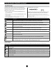
Each computer on the installation is assigned a unique Port ID. The Port ID is a one or two segment number that is determined by the Stage Level
and KVM port number of the KVM switch to which the computer/server is connected.
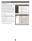
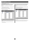
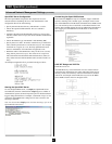
Single-Stage Installations
Single-stage installations will have a one segment Port ID consisting of two digits.
(For example, a computer/server connected to port 19 of a B064-032-04-IPG will have a Port ID of 19. A computer/server connected to port 9 of
a B064-032-04-IPG will have a Port ID of 09)
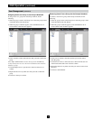
Two-Stage Installations
Two-stage installations will have a two segment Port ID consisting of 4 digits. (2 digits per segment)
• TherstsegmentofthePortIDrepresentstheportnumberoftherst-stageKVMswitchtowhichthecascadedunitisconnected.
• ThesecondsegmentofthePortIDrepresentstheportnumberofthesecond-stageKVMswitchtowhichthecomputer/serverisconnected.
(For example, a computer attached to port 3 of a second-stage KVM switch that is connected to port 15 of the first-stage KVM switch will have a
Port ID of 03-15)
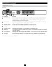
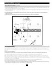
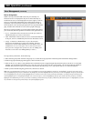
Two-Stage Installation (continued)
Hot Plugging
Powering Off & Restarting
Port ID Numbering
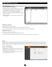
Hardware Setup (continued)
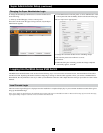
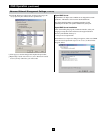
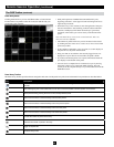
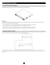
5. Plug the power cord that came with the cascaded KVM switch into its power socket, and then into a Tripp Lite Surge Suppressor,
Uninterruptible Power Supply (UPS) or PDU.
6. Repeat these steps for any other second-stage units you wish to connect.
7. First power on the first-stage KVM Switch and then power on all second-stage KVM switches.
8. Turn on the power to all of the connected computers/servers.
Note: The Power On sequence requires that the first-stage KVM Switch be powered on first. After the first-stage KVM Switch has been powered
on, all second-stage units must be powered on. After the second-stage units have been powered on, the connected computers/servers can be
powered on.