


How TR-in-FE Works 2-3
How TR-in-FE Works
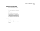
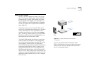
Figure 2-1 shows a diagram of a basic TR-in-FE sys-
tem. The illustration depicts three Switch 2000 TRs
interfacing with a Switch 3000 through the Token
Ring-in-Fast Ethernet Module. In this example, the
Switch 3000 acts as an 800 Mbps point of aggrega-
tion for this system with multiple FDX Fast Ethernet
pipes feeding it.
Traffic that enters a port on the Token Ring switch
and that is not destined for another port on the same
switch is directed at the TR-in-FE Module. Subse-
quently, the module puts a Fast Ethernet wrapper
(see “Tunneling” section below) on the native Token
Ring frame, and forwards the modified packet as a
Fast Ethernet frame to the Switch 3000.
The Switch 3000 handles the frame as it would any
other FE frame and forwards it to the appropriate
port. If the destination address is another TR end sta-
tion located on another switch, the destination
TR-in-FE Module strips the frame of the Fast Ethernet
information and sends the native TR frame to the
appropriate destination port. If the destination is a
Fast Ethernet attached server, the Fast Ethernet NIC
with a TR-in-FE driver interprets the frame before pro-
viding it to upper level applications. The fact that the
application communicates using TR-in-FE is transpar-
ent to the user.
Figure 2-1 A Simple Token Ring-in-Fast Ethernet
Configuration
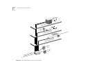
Figure 2-2 illustrates another example of Token
Ring-in-Fast Ethernet, but one on a scale more exem-
plary of what a real user configuration looks like as
part of an integrated system.
Fast Ethernet
Server
Fiber
Copper
SuperStack II
Switch 3000 TX
SuperStack II
Switch 2000 TR