3-4 CHAPTER 3: INSTALLING AND SETTING UP THE MODULE
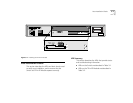
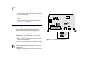
Table 3-1 Front Panel LEDs on the Switch 2000 TR
The following table describes the LED functions on
the TR-in-FE Module.
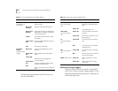
Table 3-2 LEDs on the TR-in-FE Module Panel
Checking the Power Supply
Check the MGMT LED on the Switch. If the MGMT
LED is not lit, there is a power supply problem. Try the
following troubleshooting procedures, restarting the
Switch after each step:
LED Name Color/State Indicates
MGMT
(On the front of
the Switch)
Green ON
Green fast
flashing
Green slow
flashing
Yellow
Yellow flash-
ing
OFF
Switch and TR-in-FE Module are oper-
ating normally.
Software download taking place.
The Switch and TR-in-FE Module are
initializing (for example, undergoing
a Power On Self Test).
The Switch failed its Power On Self
Test (POST).
TR-in-FE Module failed its Power On
Self Test (POST).
No power to the Switch.
Downlink
Status
(On front of the
Switch)
Green ON
Green flash-
ing
Yellow ON
Yellow flash-
ing
OFF
TR-in-FE port enabled and a link is
present.
Link present but TR-in-FE port dis-
abled.
Switch has not recognized the
TR-in-FE Module.
The TR-in-FE Module has failed the
Power On Self Test (POST).
A link is not present on the TR-in-FE
port.
LED Name Color/State Indicates
Full Duplex
(On TR-in-FE Mod-
ule)
Green ON
Green OFF
Full duplex link is on (port con-
figured for full duplex opera-
tion).
Half duplex link is on.
Port Status
(On TR-in-FE Mod-
ule)
Green ON
Green OFF
A link is present on the Ether-
net port.
The Link is not present on the
Ethernet Port.
TX
(On TR-in-FE Mod-
ule)
Yellow ON
OFF
The TR-in-FE port is transmit-
ting.
The TR-in-FE port is not trans-
mitting frames.
RX
(On TR-in-FE Mod-
ule)
Yellow ON
OFF
The TR-in-FE port is receiving
frames.
The TR-in-FE port is not receiv-
ing incoming frames.
MDIX (copper only) Green ON RJ-45 configured as a cross-
over.
Green OFF RJ-45 configured as a static
connector.


