


C-2 APPENDIX C: TR-IN-FE MODULE TECHNICAL SPECIFICATIONS
Maximum attenuation includes attenuation and the
loss induced by other components such as connec-
tors, splices, and the mating of unlike fiber types.
Although some 2 km (1.25 miles) cables have a total
attenuation of less than 11.0 dB, the 2 km (1.25
miles) inter-station distance must be maintained to
comply with modal bandwidth requirements.
The maximum attenuation value in this table is based
on a cable diameter of 62.5, 80 or 100
mm.
The following table shows alternative Multi-Mode
fiber types that can be used.
If you are using fiber with a diameter of 50 mm and
have 3Com equipment at both ends of the link, sub-
stitute 8.0 dB for the maximum attenuation. If 3Com
equipment is only at one end, substitute 6.0 dB for
the maximum attenuation value.
If you are using equipment at the end of the link from
a vendor other than 3Com, you must perform a sepa-
rate loss budget analysis. Contact the vendor(s) for
values to use in your analysis.
Does the Cable Provide Sufficient Bandwidth?
Bandwidth for multi-mode fiber is referred to as
modal bandwidth because it varies with the modal
field (or core diameter) of the fiber.
Modal bandwidth is specified in units of MHz.km,
which indicates the amount of bandwidth supported
by the fiber for a 1 km (0.625 miles) distance. Your
cable must have a Modal bandwidth of 500 MHz,
which allows the cable to support end-to-end band-
width of 250 MHz at the maximum 2 km (1.25 miles)
distance.
To check that the bandwidth of your fiber is within an
acceptable range:
1 Divide the amount of bandwidth available according
to the fiber specification by the total length of fiber
(km).
2 If the result is lower than 250 MHz, the link may be
prone to bit errors. You should shorten the length of
the fiber or use a different fiber until the result of the
calculation reaches 250 MHz.
Example
A cable with modal bandwidth of 500 MHz.km will
have 250 MHz of bandwidth at 2 km (1.25 miles).
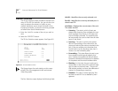
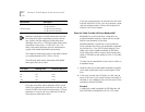
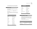
Output power (from transceiver) -20 dB minimum
-14 db maximum
Receiver power -31 dB minimum sensitivity
-14 dB maximum sensitivity
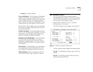
Core (mm) Cladding (mm) Numerical Aperture
50 125 0.20
50 125 0.22
85 125 0.28
100 140 0.29
Specification Description