


About the Switch 4200 Series 15
negotiated with the link partner. Alternatively, auto-negotiation can be
disabled and the flow control setting can be manually configured.
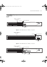
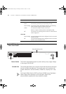
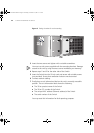
LEDs Table 4 lists LEDs visible on the front of the Switch, and how to read their
status according to color. For information on using the LEDs for problem
solving, see
“Solving Problems Indicated by LEDs” on page 54.
It is not possible to determine the duplex mode from the LEDs. For more
detailed information, refer to the “SuperStack
3 Switch Management
Interface Reference Guide” on the CD-ROM that is supplied with the
Switch.
Table 4 LED behavior
LED Color Indicates
Port Status LEDs 10BASE-T/100BASE-TX ports
Green A 100 Mbps link is present and the port is enabled.
Green flashing Packets are being transmitted/received on the port.
Yellow A 10 Mbps link is present and the port is enabled.
Yellow flashing Packets are being transmitted/received on the port.
Green / Yellow
alternating
A 10 or 100 Mbps link is present, but the port is disabled.
Off No link is present.
Port Status LEDs SFP ports
Green A 1000 Mbps link is present and the port is enabled.
Green flashing Packets are being transmitted/received on the port.
Port Status LEDs 10/100/1000BASE-T ports
Green A 1000 Mbps link is present and the port is enabled.
Green flashing Packets are being transmitted/received on the port.
Yellow A 10 or 100 Mbps link is present and the port is enabled.
Yellow flashing Packets are being transmitted/received on the port.
Green / Yellow
alternating
A 10, 100 or 1000 Mbps link present but disabled.
Off No link is present.
Unit LEDs
1–4 Green When the Switch forms a stack with other Switch 4200
Family units the LED indicates the position of the unit in the
stack and that a link is present. Unit LED number 1 can also
indicate a stand-alone Switch.
Off The Switch initialization process is not complete.
DUA1730-0AAA03.book Page 15 Thursday, November 17, 2005 12:17 PM