


Installation
40
Powerware
®
Prestige Series Installation andOperator’sManual forIBM Applications (3000 VA) Uncontrolled Copy
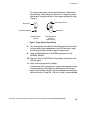
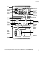
12. For the AS/400 interface, plug the AS/400 communications
cable into the serial port on the UPS rear panel. Plug the other
end of the cable into the J14 connector or the connector labeled
“UPS” on your AS/400.
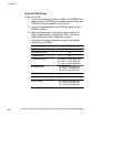
Specific locations of the J14 serial port are listed below
according to the AS/400 model:
AS/400 Models 3xx/5xx - located on the base power supply
on the back of the system unit
AS/400 Models 600/S10/620/S20 - on the power supply
AS/400 Models 640/S30/650/S40/SB1 - on the right side of the
regulator cage in the back of the tower
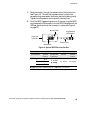
13. The equipment to be protected by the UPS should be powered
off. Plug the equipment into the power output receptacles on
the PPDM rear panel.
NOTES
Use the IEC 320-C19/C20 output cord provided with the PPDM to connect the
AS/400 to the PPDM.
You may have to use the output cord provided with the PPDM for 230V usage.
The AS/400 line cord should be used from the PPDM input connector to the wall
outlet (see Step 4 on page 43). Some configurations require the input cord
provided with PPDM.
When using the PPDM, it is recommended that the equipment not be plugged
into the UPS cabinet.
Do not protect laser printers with the UPS/PPDM because of the exceptionally
high cyclic power requirements of the heating elements.
14. If you are using a Remote Emergency Power-Off switch, follow
the instructions in “REPO Installation” on page 44.
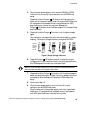
15. Start the UPS according to the following “UPS with PPDM
Startup” procedure.