


Communication
65
Powerware
®
Prestige Series Installation andOperator’sManual forIBM Applications (3000 VA) Uncontrolled Copy
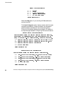
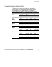
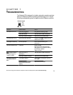
Communications Mode Reference Chart
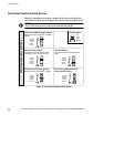
The following chart defines the UPS serial port contacts. Serial
communication is not available with 3Com and AS/400 network
configurations. Use only the applicable pins for the selected
communication mode; otherwise, interference problems may occur.
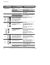
Communication Mode Function Signal Name Pin No. True Condition
Serial
Data to UPS RS232 TxD 2 N/A
Data from UPS RS232 RxD 3 N/A
Signal Ground 7
Novell
(
D
f
l
)
Battery On ON.AC 14/16 Open
(Default)
Low Battery
TWO.MIN 23/24 Closed
Signal Ground 7/15/25
Novell
(
C
)
Battery On ON.AC 14/16 Closed
(Custom)
Low Battery
TWO.MIN 23/24 Closed
Signal Ground 7/15/25
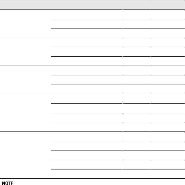
3Com
(
D
f
l
)
Shutdown (Remote) SHUT.DOWN 2 Positive Voltage
(Default)
Low Battery
LOW.BATT 9 Positive Voltage
Battery On PWR.FAIL 10 Positive Voltage
Signal Ground 7
AS/400
UPS Available UPS Available 11/13 Closed
Battery On Utility Failure 14/16 Closed
Bypass UPS Offline 17/19 Closed
Low Battery Low Battery 23/24 Closed
Signal Ground 12/15/18/25
Pin numbers separated by a forward slash ( / ) are connected together internally.