


60 8e6 ThreaT analysis reporTer Quick sTarT Guide
led indiCators and Buttons
SL and MSA Units
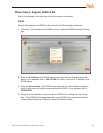
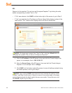
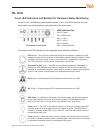
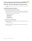
Front LED Indicators and Buttons for Hardware Status Monitoring
LED indicators and buttons for hardware status monitoring display on the front panel,
located on the right side of the SL and MSA chassis (see diagrams below).
SL chassis control panel
LED Indicator Key
PWR = Power
HD = HDD Activity
NIC1 = LAN 1
NIC2 = LAN 2
OH = Overheat
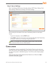
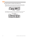
MSA chassis control panel
LED Indicator Key Button Key
A = Power F = Reset
B = HDD Activity G = Power
C = LAN 1
D = LAN 2
E = Overheat
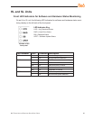
LED indicators alert you to the status of a feature on the unit while buttons let you per-
form a function on the unit.
LED Indicator Color Condition Description
Power Green On System On
Off System Off
HDD Amber Blinking HDD Activity
Off No HDD Activity
LAN 1 & LAN 2 Green On Link Connected
Blinking LAN Activity
Off Disconnected
Overheat Red On System Overheated
Off System Normal