


8e6 ThreaT analysis reporTer Quick sTarT Guide 61
HL Unit
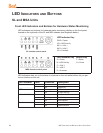
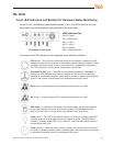
Front LED Indicators and Buttons for Hardware Status Monitoring
On an HL unit, the following control panel buttons, icons, and LED indicators for hard-
ware status monitoring display on the right side of the front panel:
HL chassis control panel
LED Indicator Key
PWR = Power
HD = HDD Activity
NIC1 = LAN 1
NIC2 = LAN 2
OH = Overheat
UID = Unique IDentier
The buttons and LED indicators for the depicted icons function as follows:
UID (button) – On an HL unit, when the UID button is pressed, a steady blue LED
displays on both the front and rear of the chassis (see also Rear of Chassis). These
indicators are used for easy location of the chassis in a large stack conguration.
The LED remains on until the button is pressed a second time.
Overheat/Fan Fail (icon) – This LED is unlit unless the chassis is overheated. A
ashing red LED indicates a fan failure. A steady red LED (on and not ashing)
indicates an overheating condition, which may be caused by cables obstructing the
airow in the system or the ambient room temperature being too warm.
NIC2 (icon) – A ashing green LED indicates network activity on LAN2.
NIC1 (icon) – A ashing green LED indicates network activity on LAN1.
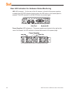
HDD (icon) – In addition to displaying in the control panel, this icon also displays
on the front panel on each hard drive carrier. A green LED indicates hard drive
activity. An unlit LED on a drive carrier may indicate a hard drive failure.
Power (icon) – The LED is unlit when the server is turned off. A steady green LED
indicates power is being supplied to the unit’s power supplies. (See also Rear of
Chassis.) A steady amber LED—or an unlit LED—may indicate a disconnected or
loose power supply cord.
Power (button) – When the power button is pressed, the main power to the server
is turned on. When the power button is pressed again, the main power to the server
is removed but standby power is still supplied to the server.