


68 8e6 ThreaT analysis reporTer Quick sTarT Guide
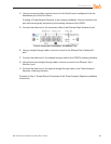
Tap insTallaTion
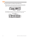
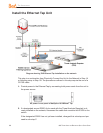
Install the Ethernet Tap Unit
Diagram showing TAR Ethernet Tap installation on the network
This step is a continuation from Physically Connect the Unit to the Network in Step 1A
or following setup in Step 1B. The procedures outlined in this step require the use of a
CAT-5E cable.
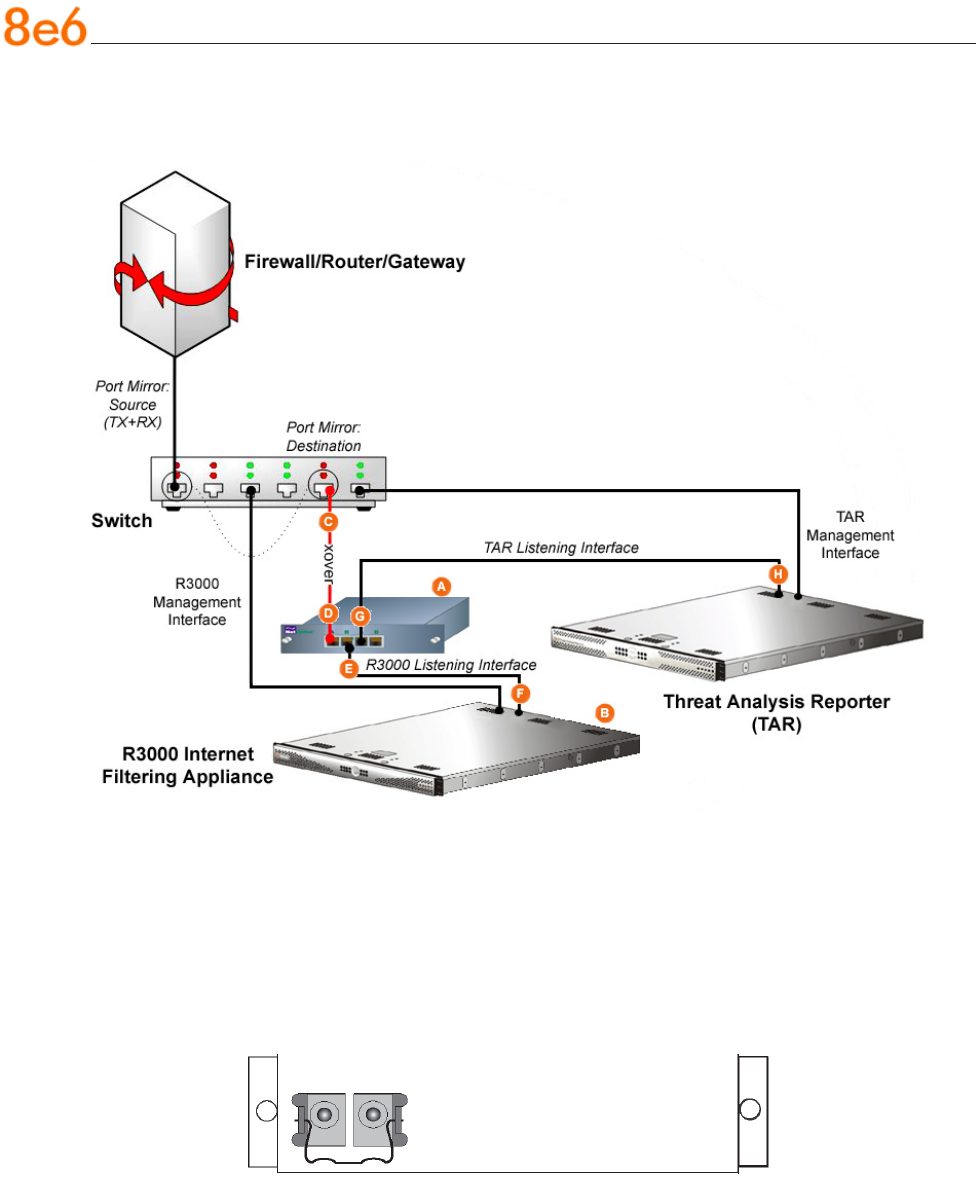
A. Provide power to the Ethernet Tap by connecting both power cords from the unit to
the power source.
AC power in rear panel of NetOptics 10/100BaseT Tap
B. If a designated source R3000 (to be used with the Threat Analysis Reporter) is al-
ready installed on the network, disconnect the cable that connects this R3000 to the
switch.
If the designated R3000 has not yet been installed, disregard this sub-step and pro-
ceed to sub-step C.