


Chapter 3 59
Disassembly Procedure Flowchart
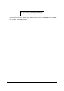
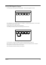
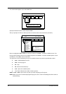
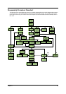
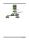
The flowchart on the succeeding page gives you a graphic representation on the entire disassembly sequence
and instructs you on the components that need to be removed during servicing. For example, if you want to
remove the main board, you must first remove the keyboard, then disassemble the inside assembly frame in
that order.
Bat tery
START
Middle Cover
W/ Launch
Board
Main Board
PCMCIA SlotI/O Port Plate
CD-ROM
Dr i ve
CD-ROM
Drive Bracket
Touch Pad
Frame
Ax2
Keyboard
Jx1
Dx 2
Mx1
Jx2
Nx 2
CD-ROM
Module
Ax 2
L1x2
L2X2
Ix2
Antennas
(Optional)
Ax 9
Ex1
Ex3
Ex4
Fx4
Ex3
Launch Board
Dx 2
CPU Heat
Sink
CPU
Cx 2
Heat Plate
Modem Cover
Touch Pad
Board
Touch Pad
But ton
Speaker s
FDD Module
Modem Board
DI MM
DIMM Cover
Bx 2
LCD Module
(See Next Page)
HDD Dummy
Cover
HDD
HDD Bracket
Ax 1
Kx 2
HDD Module
Ax 2
Touch Pad
Scroll Key
Touch Pad
FPC
Upper Case
Audio Board
PCMCIA Plate
Fan Module
Charger Plate
Wireless LAN
Board (Optional)
RTC Battery