


Chapter 3 89
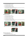
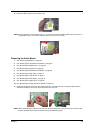
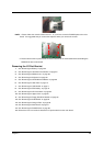
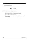
NOTE: 1. Please follow the numeric orders such as 1, 2, 3, and 4 to screw the PCMCIA plate to the main
board. It is suggested that you reverse the sequence when you remove the screws.
2. Please note that the I/O port bracket should be attached to the main board before assembling the
PCMCIA slot to the main board.
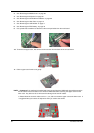
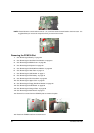
Removing the I/O Port Bracket
1. See “Removing the Battery” on page 62
2. See “Removing the Hard Disk Drive Module” on page 63
3. See “Removing the Middle Cover” on page 68
4. See “Removing the Keyboard” on page 69
5. See “Removing the CD-ROM Drive Module” on page 69
6. See “Removing the Heat Plate” on page 70
7. See “Removing the LCD Module” on page 71
8. See “Removing the RTC Battery” on page 79
9. See “Removing the CPU Heat Sink” on page 80
10. See “Removing the Upper Case” on page 81
11. See “Removing the Floppy Disk Drive Module” on page 84
12. See “Removing the Audio Board” on page 85
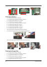
13. See “Removing the Charger Plate” on page 86
14. See “Removing the Main Board” on page 87
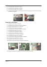
15. See “Removing the PCMCIA Slot” on page 88
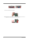
16. Remove the four hex screws to detach the I/O port bracket from the main board.